_GOTOBOTTOM
Cars
Discuss all types of automotive modeling here.
Aoshima Mad Max 2 Interceptor build review
HARV
#012
_VISITCOMMUNITY
Wyoming, United States
Joined: November 07, 2003
KitMaker: 3,098 posts
Auto Modeler: 182 posts
Posted: Thursday, April 10, 2014 - 12:02 PM UTC
My life fades, the vision dims. All that remains are memories. I remember a time of chaos, ruined dreams, this wasted land. But most of all, I remember the road warrior, the man we called Max. To understand who he was we have to go back to the other time. When the world was powered by the black fuel, and the desert sprouted great cities of pipe and steel. Gone now, swept away. For reasons long forgotten two mighty warrior tribes went to war and touched off a blaze which engulfed them all. Without fuel they were nothing. They'd built a house of straw. The thundering machines sputtered and stopped. Their leaders talked and talked and talked, but nothing could stem the avalanche. Their world crumbled. Cities exploded. A whirlwind of looting, a firestorm of fear. Men began to feed on men.

On the roads it was a white-line nightmare. Only those mobile enough to scavenge, brutal enough to pillage would survive. The gangs took over the highways, ready to wage war for a tank of juice. And in this maelstrom of decay, ordinary men were battered and smashed. Men like Max, the warrior Max. In the roar of an engine, he lost everything, and became a shell of a man. A burnt-out, desolate man. A man haunted by the demons of his past. A man who wandered out into the wasteland. And it was here, in this blighted place, that he learned to live again. *

* Opening narrative from the movie "The Road Warrior".

Untitled


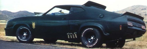
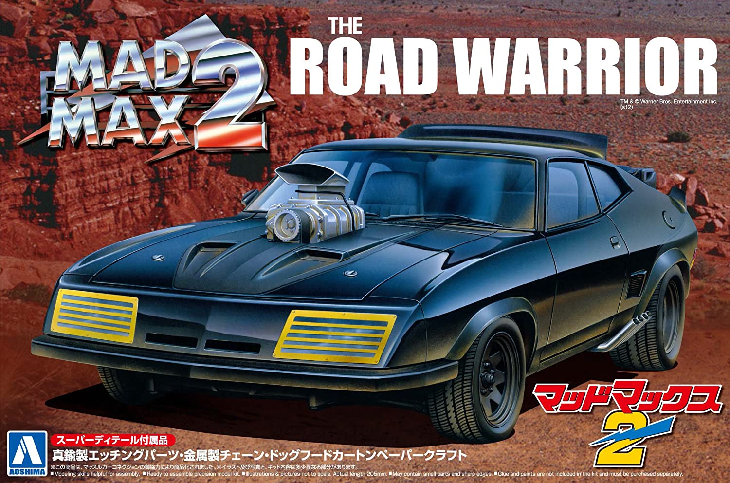
I received this kit and was asked to do a build review of it. Needless to say I was excited for the chance as "The Road Warrior" is one of all-time favorite movies. Aoshima Models has released The Road Warrior Mad Max 2 Interceptor 1973 XB GT Ford Falcon Coupe Kit as a 1:24 scale kit. The kit comes with the main car body as well as 13 sprues of molded black styrene, 2 sprues of clear styrene, 5 rubber tires, 4 plastic sleeves for mounting the wheels to the axles, 1 sheet of photo-etched brass with 21 total pieces, 1 sheet of water slide decals, 1 piece of fiber-board which contains 2 pre-cut punch out Dinky Di dog food boxes, a 6 inch length of scale chain and an instruction sheet for the photo-etched brass pieces. The kit did not come with any instructions for building the kit. I believe that I was at least the 4th person in the chain of getting this kit and it was opened when I received it. So I don't know if the instructions were lost along the way or weren't included with the kit to begin with. Luckily I was able to locate a copy of the instructions on-line.

For the beginning of the build blog I am simply going to show photographs of all of the contents of the kit.


I plan on having a few in-progress photographs and an update posted this weekend.

Thank you for following my build. This is the first Build Blog that I have done, so hopefully I will do okay with it.

Randy
russamotto
_VISITCOMMUNITY
Utah, United States
Joined: December 14, 2007
KitMaker: 3,389 posts
Auto Modeler: 50 posts
Posted: Thursday, April 10, 2014 - 01:43 PM UTC
I'll follow. That's quite a kit Aoshima have provided. I didn't realize it included the etch and extra accessories.
AussieReg
Staff MemberAssociate Editor
AUTOMODELER
#007
_VISITCOMMUNITY
Victoria, Australia
Joined: June 09, 2009
KitMaker: 8,156 posts
Auto Modeler: 2,953 posts
Posted: Friday, April 11, 2014 - 02:19 PM UTC
I'm following Harv, one of my favorite movies and I still see quite a few of these old coupes on the road here!
I will have a look around for one of these to add to the stash as well.
Looking forward to progress reports.

Cheers, D
HARV
#012
_VISITCOMMUNITY
Wyoming, United States
Joined: November 07, 2003
KitMaker: 3,098 posts
Auto Modeler: 182 posts
Posted: Thursday, April 17, 2014 - 02:46 PM UTC

Quoted Text

I'll follow. That's quite a kit Aoshima have provided. I didn't realize it included the etch and extra accessories.


Thank you Russ. I hope to do those extra details justice in the build.


Quoted Text

I'm following Harv, one of my favorite movies and I still see quite a few of these old coupes on the road here!
I will have a look around for one of these to add to the stash as well.
Looking forward to progress reports.


Thank you Damian. Glad to have you and Russ following along. One of the best movies ever and it made me want to move to Australia!! Any chance you could send one of those Ford Falcons to Wyoming that you see driving around??!! I would love to build a 1/1 scale replica of the Interceptor and have it sitting in my driveway!!

Sorry for the delay in getting this build going everyone. Been a rough couple of weeks and I have been working a lot of extra shifts at work due to staff shortages. Hopefully things will calm down and I can get going on it by this weekend. Thank you for your patience.

Thanks,
Randy
RussellE
#306
_VISITCOMMUNITY
Victoria, Australia
Joined: June 27, 2010
KitMaker: 3,959 posts
Auto Modeler: 495 posts
Posted: Thursday, April 24, 2014 - 11:31 PM UTC
My all time favourite car, Randy & one of my favourite movies. (Just a pity they didnt make more of them (the car) as they're sooo expensive now-probably due in no small part to the movie).

Watching with interest
HARV
#012
_VISITCOMMUNITY
Wyoming, United States
Joined: November 07, 2003
KitMaker: 3,098 posts
Auto Modeler: 182 posts
Posted: Friday, April 25, 2014 - 02:58 PM UTC
[quote]My all time favourite car, Randy & one of my favourite movies. (Just a pity they didnt make more of them (the car) as they're sooo expensive now-probably due in no small part to the movie).

Watching with interest [/quote

Thanks for the interest Russell. Hope you enjoy my blog.

Thanks,
Randy

HARV
#012
_VISITCOMMUNITY
Wyoming, United States
Joined: November 07, 2003
KitMaker: 3,098 posts
Auto Modeler: 182 posts
Posted: Friday, April 25, 2014 - 03:10 PM UTC
Okay guys. Things have kind of calmed down at work. Only had 2 days off so far this month!! Personal life is still a complete mess but that is another sad sad confusing tearful story. Anyway....I actually have a couple of days off so I am going to get started on the build tomorrow. I am hoping to at least have steps 1 through 7 done for sure this weekend. Maybe up through step 10........we'll see!! There are a total of 14 steps but some of those will obviously have sub-steps due to painting.

So anyway...knock on wood....there should be some progress tomorrow finally!! Sorry for the delay everyone.

Thanks,
Randy
russamotto
_VISITCOMMUNITY
Utah, United States
Joined: December 14, 2007
KitMaker: 3,389 posts
Auto Modeler: 50 posts
Posted: Saturday, April 26, 2014 - 03:15 AM UTC
Good luck with the build. Hopefully the foul weather will not interfere.
HARV
#012
_VISITCOMMUNITY
Wyoming, United States
Joined: November 07, 2003
KitMaker: 3,098 posts
Auto Modeler: 182 posts
Posted: Sunday, April 27, 2014 - 09:38 AM UTC

Quoted Text

Good luck with the build. Hopefully the foul weather will not interfere.


Thank you Russ. I finally got started on it today. The weather is the main reason why my pictures aren't the best. Raining and windy outside so I had to settle for "Man Cave" lighting when I took them.

Thanks,
Randy
HARV
#012
_VISITCOMMUNITY
Wyoming, United States
Joined: November 07, 2003
KitMaker: 3,098 posts
Auto Modeler: 182 posts
Posted: Sunday, April 27, 2014 - 10:03 AM UTC
Okay, after a few weeks of down time, I finally got around to starting on this build. I apologize up front for the photography.

Step 1. Seemed like a good place to start. Step 1 dealt with the assembly of the front brakes. There are a total of six pieces, three per brake. All of the pieces were easy to remove from the sprue and contained very little flash and seam lines and contain nice detailing. The instructions for the step are brief but detailed for the construction of the brake assemblies. Specific painting details are pointed out with a number designating the correct color to use from the provided painting guide. All of the pieces fit together well without any sanding or filing needed. For Step 2 it is pointed out in the instructions that it is important to keep the left and right assemblies identified so that the correct one goes on the correct side of the chassis.


The brake assemblies. One completed and one not.

Well, so much for Step 1.

Thanks,
Randy
HARV
#012
_VISITCOMMUNITY
Wyoming, United States
Joined: November 07, 2003
KitMaker: 3,098 posts
Auto Modeler: 182 posts
Posted: Sunday, April 27, 2014 - 10:19 AM UTC
Step 2. Step 2 dealt with the assembly of the front axle and attaching the brake assemblies to the chassis. There are a total of five pieces, counting the two completed brake assemblies from Step 1. All of the pieces were easy to remove from the sprue and contained very little flash and seam lines and contain nice detailing. The instructions for the step are brief but detailed for the construction. Specific painting details are pointed out with a number designating the correct color to use from the provided painting guide. All of the pieces fit together well without any sanding or filing needed. I did have a little trouble getting Part 15 to clip on to the right (R) brake assembly. It took me 3 to 4 times of squeezing before the two parts clicked together. It could have just been from me being leary of squeezing too hard in fear of breaking something. However, Part 15 clicked on to the left (L) brake assembly easily on the first attempt without issue. Just a minor thing but I thought it should be mentioned. The brake assemblies are attached without glue so that the front wheel assemblies will be able to turn. As mentioned in Step 1 it is important to keep the left and right assemblies identified so that the correct one goes on the correct side of the chassis. The brake assemblies and the axle pieces all mount to the chassis without problem and look nice once assembled. The instruction sheet indicates pieces that are to be glued and pieces that are not to be glued by different lines shown in the steps. A solid line indicates a glued part and a dotted line indicates a part that is not to be glued. As can be seen in the photographs, the bottom of the chassis is detailed fairly well. The bottom of the engine can be seen and the molded details such as the oil pan, headers, starter, torsion bars and the serpentine belt assembly for the fan and alternator can all be seen.


The main components for Step 2.


The main components for Step 2 with the addition of the brake assemblies.


Completed construction.


Close up of the completed assembly.

Well, that’s all for Step 2.

Thanks,
Randy
HARV
#012
_VISITCOMMUNITY
Wyoming, United States
Joined: November 07, 2003
KitMaker: 3,098 posts
Auto Modeler: 182 posts
Posted: Sunday, April 27, 2014 - 10:31 AM UTC
Step 3. Step 3 dealt with the assembly of the rear wheel assemblies. There are a total of six pieces, three per wheel assembly. All of the pieces were easy to remove from the sprue and contained very little flash and seam lines and contain nice detailing. The instructions for the step are brief but detailed for the construction of the wheel assemblies. Specific painting details are pointed out with a number designating the correct color to use from the provided painting guide. As mentioned in step 2, there are lines indicating whether to glue or not to glue. All of the pieces fit together well without any sanding or filing needed. Like in Step 1, the wheel assemblies are shown as left and right. There is no real reason for this as both assemblies are identical. As with Step 1, Step 3 was an easy step to complete.


The wheel assemblies. One completed and one not.


The completed wheel assemblies, front and back views.

That’s it for Step 3.

Thanks,
Randy
HARV
#012
_VISITCOMMUNITY
Wyoming, United States
Joined: November 07, 2003
KitMaker: 3,098 posts
Auto Modeler: 182 posts
Posted: Sunday, April 27, 2014 - 10:46 AM UTC
Step 4. Step 4 dealt with the assembly of the rear axle and wheel assemblies as well as the shock absorbers and their mounts and the exhaust system. There are a total of twelve pieces, including the wheel assemblies from Step 3. All of the pieces were easy to remove from the sprue and contained very little flash and seam lines and contain nice detailing. The instructions for the step are brief but detailed for the construction of the all of the rear axle and exhaust components. Specific painting details are pointed out with a number designating the correct color to use from the provided painting guide. The shock absorbers have pins on the ends of them for mounting to the shock absorber mounts however there are no holes for the pins to go into. All of the pieces fit together well without any sanding or filing needed. There is a reminder in the instructions to remove the chrome plating from the exhaust pipes before gluing them to the main exhaust pipes. My favorite detail of the kit so far is the little things that definitely show that this car belongs to Max. If all of you have watched “The Road Warrior” then you will be familiar with the explosive device at the rear of the car as well as the knife that is hidden near it. Both the explosive device, Part 75 and the knife, Part 110, are included in the kit much to my surprise and pleasure.


All of the components for Step 4 with the wheel assemblies from Step 3.


Step 3 completed.


Close up showing the explosive device and the knife to the left of the device. Awesome!!


The explosive device and the knife as seen in the movie.


Another view of the explosive device. “The last of the V8 Interceptors... a piece of history! Would've been a shame to blow it up”.


View of the completed step from the bottom.


View of the completed step from the top showing the exhaust pipes.

And so we come to the end of Step 4.

Thanks,
Randy
HARV
#012
_VISITCOMMUNITY
Wyoming, United States
Joined: November 07, 2003
KitMaker: 3,098 posts
Auto Modeler: 182 posts
Posted: Sunday, April 27, 2014 - 11:17 AM UTC
Step 5. Well sorry, Step 5 will be a bit boring for you. Step 5 deals with the mounting of the tires to the rims. The instructions for the step are brief but detailed for the construction of the tire/wheel assemblies. Specific painting details are pointed out with a number designating the correct color to use from the provided painting guide. I am leaving this step out until the kit is completed and painted for protection of the tires and for the ease of not having to mask them!! I will return and address this step once I am near completion of the vehicle.


Tires and rims.

The front tires are narrow and the rear tires are wide as one can see. The tires are the soft rubber type and not hard plastic and they do have nicely detailed tread on them.


The rims. Front on the left. Rear on the right.

I was pleased to see that the kit came with the correct rear rims which are different from the front rims, which is correct for the car as shown in "The Road Warrior". I will provide a photograph of the vehicle from the film to show the difference for anyone who might not have ever noticed.


Max meets the Gyro Captain. Note the difference between the front and rear rims/wheels. “A fellah, a QUICK fellah, might have a weapon under there. I'd have to pin his head to the panel”.

And so we come to a close on step 5.

Thank you everyone for following along. Thank you for your patience with waiting for me to get started on this project as well. Step 6, and beyond, will be arriving soon.

Thanks,
Randy
RussellE
#306
_VISITCOMMUNITY
Victoria, Australia
Joined: June 27, 2010
KitMaker: 3,959 posts
Auto Modeler: 495 posts
Posted: Sunday, April 27, 2014 - 10:33 PM UTC
Looking good Randy.

Is the bonnet attached to the main vehicle or seperate?
HARV
#012
_VISITCOMMUNITY
Wyoming, United States
Joined: November 07, 2003
KitMaker: 3,098 posts
Auto Modeler: 182 posts
Posted: Monday, April 28, 2014 - 12:45 AM UTC

Quoted Text

Looking good Randy.


Thank you Russell.


Quoted Text

Is the bonnet attached to the main vehicle or seperate?


The bonnet (or hood as we Yanks say ) is molded in place. For the super detailer out there I am sure it could easily be cut out to display it in the open position.

Thanks again,
Randy
HARV
#012
_VISITCOMMUNITY
Wyoming, United States
Joined: November 07, 2003
KitMaker: 3,098 posts
Auto Modeler: 182 posts
Posted: Monday, May 05, 2014 - 02:52 PM UTC
Just wanted to let everyone know that I got a few more steps completed and I plan on having the photos and narrative up tomorrow. Didn't want anyone losing interest so I thought I would put a quick little post here.

Thanks,
Randy
russamotto
_VISITCOMMUNITY
Utah, United States
Joined: December 14, 2007
KitMaker: 3,389 posts
Auto Modeler: 50 posts
Posted: Tuesday, May 06, 2014 - 12:54 AM UTC
Good to hear, Randy. I look forward to the post.
JPTRR
Staff MemberManaging Editor
RAILROAD MODELING
#051
_VISITCOMMUNITY
Tennessee, United States
Joined: December 21, 2002
KitMaker: 7,772 posts
Auto Modeler: 50 posts
Posted: Tuesday, May 06, 2014 - 01:42 AM UTC
Hi Randy,

It is looking good! I'm keeping up.

HARV
#012
_VISITCOMMUNITY
Wyoming, United States
Joined: November 07, 2003
KitMaker: 3,098 posts
Auto Modeler: 182 posts
Posted: Tuesday, May 06, 2014 - 12:32 PM UTC

Quoted Text

Good to hear, Randy. I look forward to the post.


Quoted Text

Hi Randy,

It is looking good! I'm keeping up.


Thank you Russ and Fred. I am getting ready to post four more steps in the build. Again I apologize for the photography. We are having quite the rain here in Sheridan this afternoon/evening so I had to rely on "Man Cave" lighting again tonight. One of these days I need to get a proper lighting booth.

Thanks again,
Randy
HARV
#012
_VISITCOMMUNITY
Wyoming, United States
Joined: November 07, 2003
KitMaker: 3,098 posts
Auto Modeler: 182 posts
Posted: Tuesday, May 06, 2014 - 12:40 PM UTC
Step 6. Step 6 dealt with the assembly of the blower/super charger assembly. There are a total of seven pieces. All of the pieces were easy to remove from the sprue and contained very little flash and seam lines and contain nice detailing. The instructions for the step are brief for the construction of all of the blower/super charger components. Parts 44 and 46 take a little dry fitting to ensure proper placement. Part 46 needs to be placed correctly so that the shaft for the belt assembly is on the correct side of the assembly. All of the pieces fit together well without any sanding or filing needed. There is a reminder in the instructions to remove the chrome plating from the parts before gluing them together. Part 51 is simply a tray for the blower/super charger assembly to sit on. It needs to be painted flat black so I didn’t glue the blower/super charger assembly to it until it is painted. I should note that one of my disappointments in the kit so far is the lack of an engine. A complete engine would have been a nice addition to add yet more details to the Interceptor.


That’s it for Step 6.

Thanks,
Randy
HARV
#012
_VISITCOMMUNITY
Wyoming, United States
Joined: November 07, 2003
KitMaker: 3,098 posts
Auto Modeler: 182 posts
Posted: Tuesday, May 06, 2014 - 01:06 PM UTC
Step 7. Step 7 dealt with the assembly of the headlight assemblies. There are a total of four pieces. All of the pieces were easy to remove from the sprue and contained very little flash and seam lines and contain nice detailing. The clear lenses are nice and contain realistic looking lines on the face of them. The instructions for the step are brief for the construction of the headlight assemblies which is understandable since there are only four pieces. All of the pieces fit together well without any sanding or filing needed. There is a reminder in the instructions to remove the chrome plating from the parts before gluing the lenses to the housings. The main housings need to be painted flat black but the interior of the housings need to remain chrome. I went ahead and assembled the lights as I figured it would be easier to mask the lenses than try to mask the openings.


That’s it for Step 7, short and sweet.

Thanks,
Randy
HARV
#012
_VISITCOMMUNITY
Wyoming, United States
Joined: November 07, 2003
KitMaker: 3,098 posts
Auto Modeler: 182 posts
Posted: Tuesday, May 06, 2014 - 01:52 PM UTC
Step 8. Step 8 dealt with the assembly of the dash and dashboard. There are a total of eight pieces. All of the pieces were easy to remove from the sprue and contained very little flash and seam lines and contain nice detailing. The instructions for the step are very brief for the construction of the dash and dashboard. More detailed instructions would have been nice for some of the pieces, specifically parts 66 and 77. Parts 66 and 77 are shown how they should sit above the steering column however they will not fit as shown. It took a little trial and error to get them to fit in a spot relatively close as shown in the instructions. I chose to not use part 42, the bracket for the blue revolving police light, and I used part 8 from the photo-etched brass fret in its place. The photo-etched piece was easy to remove from the fret and it bent easily and fit well. As you can see from the photos I need to go back and clean up some glue…..oops. There are no markings for the placement of the piece so the modeler will need to eyeball it and place it where it looks good to them. For the most part all of the pieces fit together well without any sanding or filing needed. The dash and dashboard pieces fit together fairly well however there are a couple of gaps that will need to be filled.


And so we come to the end of Step 8.

If you are a super geek fan, like me, you might agree with me on this side note. As I assembled the steering wheel and steering column it made me think of the Interceptor steering wheel from the original Mad Max movie. For maybe a one second shot you can see that Max placed a photograph of Jessie and Sprog (Max’s wife and son) in the center of the steering wheel. Even though it would probably be way too small to show the needed detail it would have been nice to have a decal of the photograph to place on the steering wheel.


Until Step 9.....see ya.
HARV
#012
_VISITCOMMUNITY
Wyoming, United States
Joined: November 07, 2003
KitMaker: 3,098 posts
Auto Modeler: 182 posts
Posted: Tuesday, May 06, 2014 - 02:26 PM UTC
Step 9. Step 9 dealt with the main assembly of the safety roll cage. There are a total of six pieces. All of the pieces were easy to remove from the sprue. So far these six pieces have contained the most flash and seam lines and several molding blocks of styrene. So obviously these pieces took a little more time to clean up than the other pieces so far. The instructions for the step are very brief for the construction of the roll cage. For the most part all of the pieces fit together well without any sanding or filing needed. There will need to be some filling done where the some of the pieces fit together. Step 10 will deal with mounting the roll cage to the interior of the vehicle. A recommendation I would make would be for other modelers to do like I did and use the car interior from Step 10 as a jig to hold the roll cage pieces together in the correct shape until the glue dries. I did this and it worked out very well. Other than the time required for clean-up of the pieces this was a fairly easy step.


So for step 9, that’s all folks.


This has nothing to do with the build but I wanted to share this picture from "The Road Warrior" showing the funniest scene in which you can see the roll cage.


"Good dog.....nice doggy eh"?

HARV
#012
_VISITCOMMUNITY
Wyoming, United States
Joined: November 07, 2003
KitMaker: 3,098 posts
Auto Modeler: 182 posts
Posted: Tuesday, May 06, 2014 - 02:41 PM UTC
I need to apologize to everyone. As I was placing these posts tonight, Step 6 through Step 9, I realized that I forgot to take pictures of all of the individual pieces in a group picture like I did in Step 1 through Step 5. I apologize for that and that is something that I will correct for the remaining steps.

Sorry about that everyone.

Randy
 _GOTOTOP