Trucks
Scale truck modeling topics.
Opel Blitz Custom Car Carrier
165thspc
#521
_VISITCOMMUNITY
Kentucky, United States
Joined: April 13, 2011
KitMaker: 9,465 posts
Auto Modeler: 106 posts
Posted: Saturday, August 24, 2019 - 12:13 PM UTC
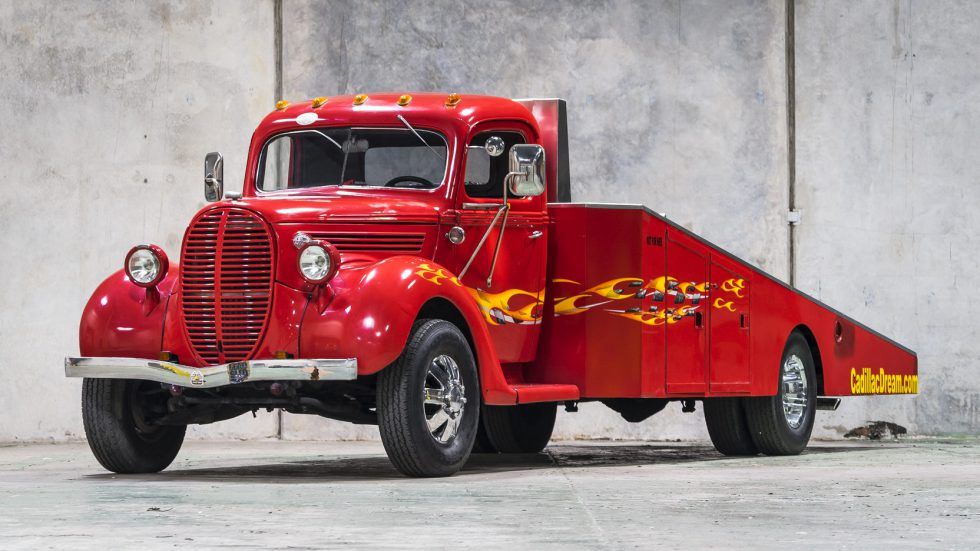
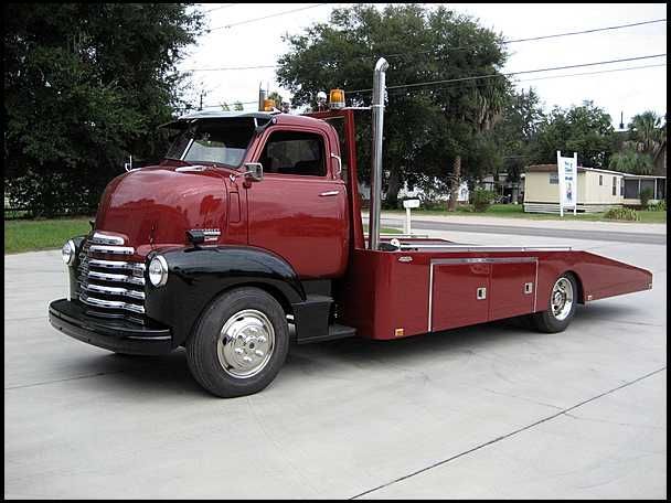
Well Damian bearing in mind that this is only a model AND that it is YOUR model and not mine, I still have to respectfully submit that achieving a 50/50 split of weight load over the rear axle would not be an exactly a safe course of action when building a real custom auto carrier. Unfortunately I cannot quote you engineering chapter and verse, instead I will simply show what others have done in the way of similar real life vehicles.

Also all engineering considerations aside, I think an extended chassis model would be only slightly more challenging construction wise but hugely more interesting visually. IMHO.

Again, no disrespect intended and not at all arguing the point - just stating an alternate view.


165thspc
#521
_VISITCOMMUNITY
Kentucky, United States
Joined: April 13, 2011
KitMaker: 9,465 posts
Auto Modeler: 106 posts
Posted: Saturday, August 24, 2019 - 12:36 PM UTC
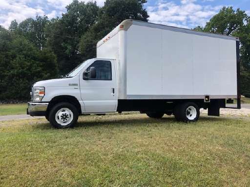
One final point: Admittedly, 2-axle straight box trucks come is all lengths and sizes but here is a fairly typical modern box truck with a cubic volume about right to function as your car carrier.

As you can see the design engineer has used best engineering practice and has placed the rear axle a bit more rearward specifically to achieve a more ideal weight distribution of the load - probably more like 60/40 rather than 50/50.

I will stop with that.

AussieReg
Staff MemberAssociate Editor
AUTOMODELER
#007
_VISITCOMMUNITY
Victoria, Australia
Joined: June 09, 2009
KitMaker: 8,156 posts
Auto Modeler: 2,953 posts
Posted: Saturday, August 24, 2019 - 12:42 PM UTC
Hi Mike.

Excellent images, and I can see what you mean now, most of these have the car front wheels about midway between the rear axle and cab of the truck, and the car rear wheels just behind the truck rear axle.

I just did a quick mock-up with the truck and the '53 Corvette, and to achieve this sort of balance I will need to add a good 35-40mm to the chassis length. This will be easy to do now before I start adding the other parts. A question though, adding what amounts to almost 1 metre in 1:1 terms, how would the lengthened drive shaft cope with the torque? Perhaps I should add a transfer case and a second short shaft rather than just add the length to the existing part, or alternatively scratch up a heavier shaft?

When I look at my first reference shot, the overhang of the "wedge" behind the rear wheel looks a bit excessive and a bit ungainly. I think lengthening the chassis now is the best course of action to get a much more attractive proportion on the wedge.

Once again, I really appreciate the input and am always happy to take advice from those who have gone down this path before me!

Cheers, D
165thspc
#521
_VISITCOMMUNITY
Kentucky, United States
Joined: April 13, 2011
KitMaker: 9,465 posts
Auto Modeler: 106 posts
Posted: Saturday, August 24, 2019 - 01:00 PM UTC
Normally an overly long driveshaft will be instead broken into two shorter shafts with a "pillow block", frame mounted bearing supporting the center of the driveshaft assembly. This two part drive shaft does not have to be two parts of equal length. The two shafts can be split at any convent length to allow the pillow block to be mounted on an existing frame cross member.

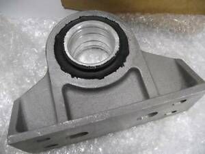
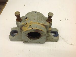
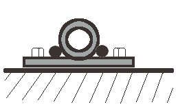
Here are a couple of typical pillow bearings. On your application there would be a universal joint on each side of this bearing connected to each driveshaft. (The bearing is fairly easy to scratch build.)

Keep an eye out for long 2-axle box trucks around you home area - you will no doubt easily find several having split, two part driveshafts with a very visible pillow block hanging down from the frame in plain sight.

.
165thspc
#521
_VISITCOMMUNITY
Kentucky, United States
Joined: April 13, 2011
KitMaker: 9,465 posts
Auto Modeler: 106 posts
Posted: Saturday, August 24, 2019 - 01:17 PM UTC
A little Evergreen tubing, some rod and an appropriately sized flat plate, then add a couple of bolt castings. (Or some short lengths of Evergreen hexagonal rod used for bolts.)


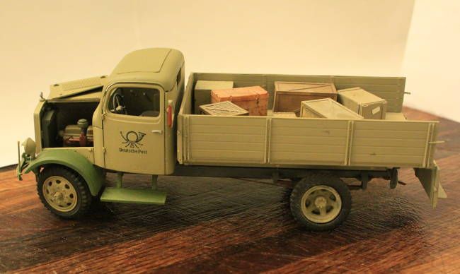
Italeri does a Mercedes 4x2 truck in 1/35th. The cab molding is excellent but the chassis is nothing but their Opel Blitz molding repackaged. I decided to Mercedes-ize the frame and chassis and one big difference is that Mercedes used a two part drive shaft with pillow block bearing.
So here we are . . . . .


Not a great model but I was pleased with my little post-war Deutschepost mail delivery truck.
AussieReg
Staff MemberAssociate Editor
AUTOMODELER
#007
_VISITCOMMUNITY
Victoria, Australia
Joined: June 09, 2009
KitMaker: 8,156 posts
Auto Modeler: 2,953 posts
Posted: Saturday, August 24, 2019 - 03:19 PM UTC
Great info Mike, you've set me on a mission. Many thanks once again.

Cheers, D
Joel_W
Staff MemberAssociate Editor
AUTOMODELER
_VISITCOMMUNITY
New York, United States
Joined: December 04, 2010
KitMaker: 11,666 posts
Auto Modeler: 2,974 posts
Posted: Sunday, August 25, 2019 - 01:10 AM UTC
D,
The technical info to closer replicate what would be more realistic certainly has caught my attention.

I'm looking forward to what your decisions will be, and how you go about the needed modifications.


Joel
AussieReg
Staff MemberAssociate Editor
AUTOMODELER
#007
_VISITCOMMUNITY
Victoria, Australia
Joined: June 09, 2009
KitMaker: 8,156 posts
Auto Modeler: 2,953 posts
Posted: Sunday, August 25, 2019 - 02:10 AM UTC

Quoted Text

I'm looking forward to what your decisions will be, and how you go about the needed modifications.


Well I won't keep you waiting Joel!

First up, chose a spot and chop chop!


I have a decent selection of Evergreen sheet and profile on hand, so I dug around and found a sheet with the same thickness as the chassis rails, then cut some strips to fit neatly inside the C-section. I decided to put a 40mm extension (960mm in 1:1) on the chassis, so I cut two 40mm spacers and two inner reinforcements to overlap into the chassis by 20mm each end, then cemented them together.


A little curing time, then these spacers were fixed into place on the chassis.


While this was curing I cut some 3.2mm angles to length to fit neatly between the existing cross members, and then cemented them into place top and bottom.


Once again a bit of curing time sitting on a flat surface, then checked for alignment and twist, and it seems to have held up very nicely.


The chassis extension is now supported inside and out, top and bottom, and should handle the weight of both the wedge tray and the car kit sitting on top of it.

All up, this took about an hour and I'm happy with the result.

Next up, a light sand to clean up the profiles, then use the original kit tailshaft, from the differential forward, to locate the position of the "pillow block" so kindly detailed by Mike. I will then scratch build a cross member and pillow block, and a short front tailshaft to extend the drive train forward to the transmission.

Cheers, D
165thspc
#521
_VISITCOMMUNITY
Kentucky, United States
Joined: April 13, 2011
KitMaker: 9,465 posts
Auto Modeler: 106 posts
Posted: Sunday, August 25, 2019 - 04:43 AM UTC
A BIG thumbs up Damian!

Making that first cut in an otherwise perfectly good vehicle frame is always a somewhat stressful "moment of truth"!
Joel_W
Staff MemberAssociate Editor
AUTOMODELER
_VISITCOMMUNITY
New York, United States
Joined: December 04, 2010
KitMaker: 11,666 posts
Auto Modeler: 2,974 posts
Posted: Sunday, August 25, 2019 - 05:55 AM UTC
D,
Now that's really impressive. It's both scratch building and a modification at the same time.

Joel
165thspc
#521
_VISITCOMMUNITY
Kentucky, United States
Joined: April 13, 2011
KitMaker: 9,465 posts
Auto Modeler: 106 posts
Posted: Sunday, August 25, 2019 - 07:45 AM UTC
Don't know that this really applies to you conversion . . . .

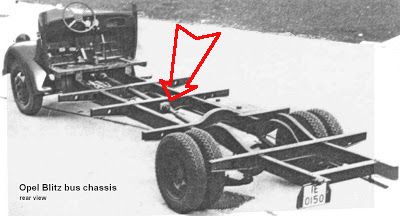
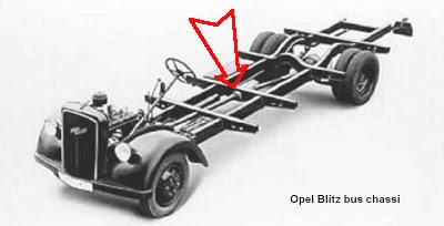
Shown here is the long frame, low floor Blitz bus chassis. In this case the drive shaft was also long enough to require a two-piece shaft with a pillow bearing a mid-ships.

In this case the floor was so low that the frame cross member totally encloses/surrounds the pillow bearing. Additionally the desired ground clearance did not allow the bearing to be hung below the frame. (I don't think this will be necessary on your vehicle but I show this here just in case such a design would become desirable.)


AussieReg
Staff MemberAssociate Editor
AUTOMODELER
#007
_VISITCOMMUNITY
Victoria, Australia
Joined: June 09, 2009
KitMaker: 8,156 posts
Auto Modeler: 2,953 posts
Posted: Sunday, August 25, 2019 - 04:03 PM UTC
More excellent reference info Mike, many thanks. I think that incorporating the pillow bearing into the cross-member will be a neat solution. I will start playing around with some designs and see what I can come up with.

Cheers, D
RussellE
#306
_VISITCOMMUNITY
Victoria, Australia
Joined: June 27, 2010
KitMaker: 3,959 posts
Auto Modeler: 495 posts
Posted: Sunday, August 25, 2019 - 06:22 PM UTC
Wow! So much going on here Damian!

Very nice work on extending the chassis!
165thspc
#521
_VISITCOMMUNITY
Kentucky, United States
Joined: April 13, 2011
KitMaker: 9,465 posts
Auto Modeler: 106 posts
Posted: Sunday, August 25, 2019 - 08:25 PM UTC
Damian, earlier you mentioned adding a transfer case to break up and shorten the two driveshafts. Do you have a spare one laying around?

Sometimes in such "shop built" conversions the builder might add an available transfer case to give themselves access to the lower "granny gear" in the T-case.

With more modern day conversions a similar looking unit might be added to give the vehicle either a two speed rear end (doubling the available gears) or an overdrive unit for better gas millage.
165thspc
#521
_VISITCOMMUNITY
Kentucky, United States
Joined: April 13, 2011
KitMaker: 9,465 posts
Auto Modeler: 106 posts
Posted: Sunday, August 25, 2019 - 08:48 PM UTC
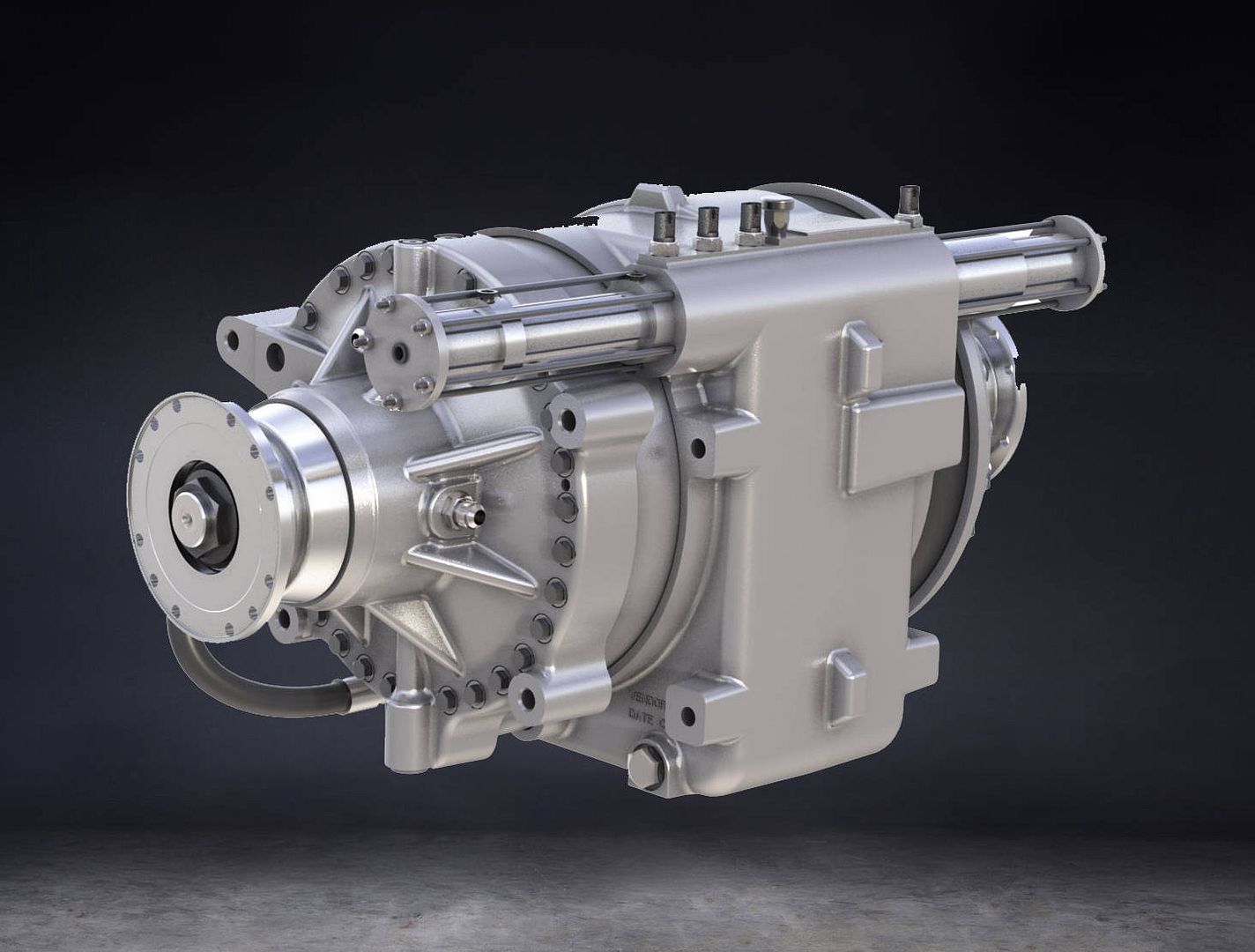
There are both after market overdrive (better gas millage) and underdrive (more pulling power) units available. Something like this could take the place of your pillow bearing, inserted anywhere along the length of the driveshaft run.

Typical after market overdrive unit:


In case you are wondering; a good "Speed Shop" will usually have a little side business going where they cut down existing driveshafts to order. This to accommodate customers doing strange or different modifications to their custom vehicles. Please know; the science of welding and balancing an altered driveshaft is not a task for a "backyard" welder and should only be done by a precision shop that seriously knows what they are doing.
AussieReg
Staff MemberAssociate Editor
AUTOMODELER
#007
_VISITCOMMUNITY
Victoria, Australia
Joined: June 09, 2009
KitMaker: 8,156 posts
Auto Modeler: 2,953 posts
Posted: Sunday, August 25, 2019 - 08:57 PM UTC

Quoted Text

Damian, earlier you mentioned adding a transfer case to break up and shorten the two driveshafts. Do you have one laying around?


Hi Mike.

I don't have one lying around, I was considering modifying the diff out of a car kit to something a bit more heavy-duty looking, but I'm pretty much set on the idea of a cross-member mounted pillow bearing now. It's going to be buried under the wedge tray so the only evidence of its existence will be this thread on Automodeler!

Cheers, D
165thspc
#521
_VISITCOMMUNITY
Kentucky, United States
Joined: April 13, 2011
KitMaker: 9,465 posts
Auto Modeler: 106 posts
Posted: Sunday, August 25, 2019 - 09:02 PM UTC
(I'm sure it will come as no surprise but I almost always sit my models on a small mirror just to show off the underbody work as well.)
Hwa-Rang
_VISITCOMMUNITY
Kobenhavn, Denmark
Joined: June 29, 2004
KitMaker: 6,760 posts
Auto Modeler: 2,182 posts
Posted: Sunday, August 25, 2019 - 11:19 PM UTC
Excellent scratch building D. Once painted you wouldn't know, is was scratch build.
AussieReg
Staff MemberAssociate Editor
AUTOMODELER
#007
_VISITCOMMUNITY
Victoria, Australia
Joined: June 09, 2009
KitMaker: 8,156 posts
Auto Modeler: 2,953 posts
Posted: Monday, August 26, 2019 - 02:01 AM UTC
Thanks for the support guys, good to know I'm on the right track.

A quick test fit of the '36 for visual proportions, I'm happy with the way it looks, and the slope of the wedge will add more interest.


Marking out for the new cross member and pillow bearing mount, it will go half way between the existing cross members (black marks).


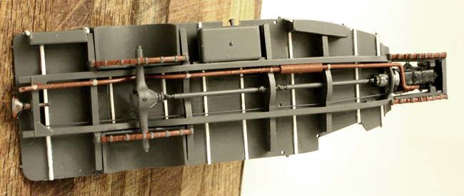
"Side View" showing the kit tailshaft part. I will cut the long section back to fit between the diff and bearing, and cut the short section back to connect through the bearing, centred around the black marks. I will scratch build a new forward tail shaft. Conveniently, the black sprue from the kit is the same diameter as the tailshaft part and there are a couple of nice long straight sections.


A piece of 3.2mm square rod is cut and trimmed to match the top section of the kit cross members, then cemented into place.


Some thin flat sheet stock is cut to shape to match the top section of the existing cross members, and extend down to house the bearing (tube stock).


Flat sheet dry-fit to check the visuals.


I'm thinking I might put some reinforcing blocks between the flat sheets and cut out some lightening holes for interest.

As always, please let me know your thoughts and all advice is gratefully accepted.

Cheers, D
Szmann
_VISITCOMMUNITY
Netherlands Antilles
Joined: September 02, 2014
KitMaker: 1,977 posts
Auto Modeler: 1,371 posts
Posted: Monday, August 26, 2019 - 07:11 PM UTC
Hi, D.!
I have missed a step here.
First off, the paint job is awesome. For what I'm concerned, I guess it's one of your best so far, together with the white pearl on the 'Vette.

On the scratch building, you and Nick are reigning supreme. Well done. Yes, I vote for lightening holes for added interest and, perhaps, realism. Some welding seams as well?

Gabriel
AussieReg
Staff MemberAssociate Editor
AUTOMODELER
#007
_VISITCOMMUNITY
Victoria, Australia
Joined: June 09, 2009
KitMaker: 8,156 posts
Auto Modeler: 2,953 posts
Posted: Tuesday, August 27, 2019 - 12:54 AM UTC
Gabriel, thanks so much for the positive feedback mate!

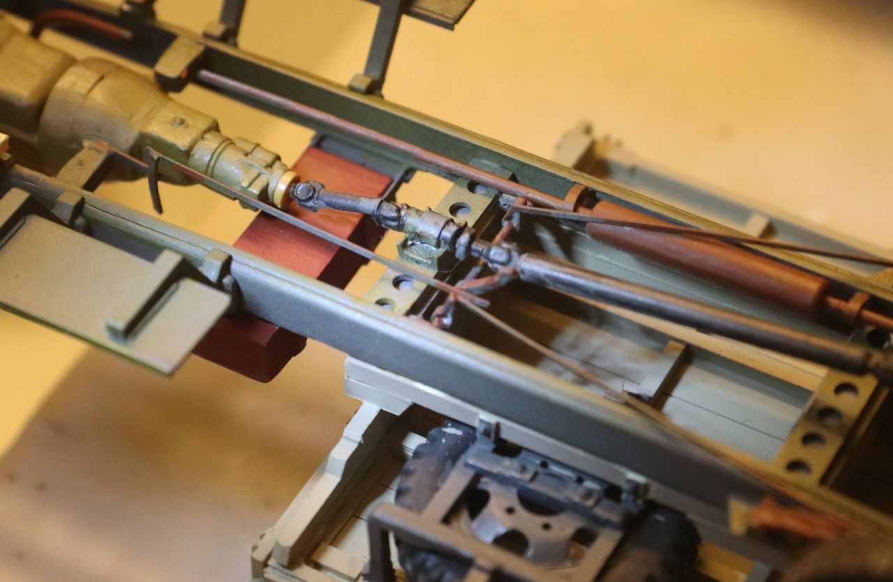
Tonight I cemented the parts of the cross member and pillow bearing in place and cut down the tailshaft to fit the rear section. The front section will be done once I get the engine/gearbox assembly painted and in place.


Cheers, D
165thspc
#521
_VISITCOMMUNITY
Kentucky, United States
Joined: April 13, 2011
KitMaker: 9,465 posts
Auto Modeler: 106 posts
Posted: Tuesday, August 27, 2019 - 12:57 AM UTC
Looks like you are really onto something there. Kudos!
Joel_W
Staff MemberAssociate Editor
AUTOMODELER
_VISITCOMMUNITY
New York, United States
Joined: December 04, 2010
KitMaker: 11,666 posts
Auto Modeler: 2,974 posts
Posted: Tuesday, August 27, 2019 - 03:25 AM UTC
D,
The modification to the drive shaft with the pillow bearing really looks like the real thing. Can't wait to see the drive train finished up.

Joel
165thspc
#521
_VISITCOMMUNITY
Kentucky, United States
Joined: April 13, 2011
KitMaker: 9,465 posts
Auto Modeler: 106 posts
Posted: Tuesday, August 27, 2019 - 04:01 AM UTC
Just a thought and minor suggestion:

Damian, as you may now be getting into the idea of a little extra underbody detail, might I suggest using some small bolt head castings (Grant Line) or even just small diameter plastic rod to now add a drain plug in the bottom of that differential as well as a check filler plug in the rear face of the diff. The check plug would be about a third of the way up the face of the rear differential cover plate and off center to one side.

Again just a minor suggestion for adding small, simple details.
RussellE
#306
_VISITCOMMUNITY
Victoria, Australia
Joined: June 27, 2010
KitMaker: 3,959 posts
Auto Modeler: 495 posts
Posted: Tuesday, August 27, 2019 - 10:30 AM UTC
Wow! Awesomenessness!