Cars: Other Racing
For automotive racing topics not already covered.
Revell 1/25 Roush IMSA Trans Am JPS Mustang
Joel_W
Staff MemberAssociate Editor
AUTOMODELER
_VISITCOMMUNITY
New York, United States
Joined: December 04, 2010
KitMaker: 11,666 posts
Auto Modeler: 2,974 posts
Posted: Thursday, November 14, 2019 - 09:15 AM UTC
It's been quite a few days since I last updated my Roush Trans Am JPS Mustang. Honestly, I haven't had much time of late between the same family issues that just never seem to get resolved, and now with the holidays approaching way to fast. But I've managed to get some work accomplished.

I still haven't rubbed out the clear coat as yet, but it's on the top of my "To Do" list this coming week. Instead, I started to focus on various parts and planning details like hoses, braided lines, and electrical lines.

I added the fuel cell, dry sump oil tank, and battery box in the trunk compartment and started to drill the necessary holes for the various lines, keeping in mind that the only viewing angle will be through the glass panel in the trunk lid that will be closed.


Then I started to focus on the driver's compartment by test fitting the rear bulkhead. There's still a few electrical boxes to be added as well as all the various wiring to add before it's glued into place. And then the right side Aluminum sheet cover that all the various lines etc. pass through rather then just being clamped to the driver compartment floor, plus the wiring for the electrical boxes on the top of it.


And that where I'm presently at.


Joel
Cosimodo
#335
_VISITCOMMUNITY
Auckland, New Zealand
Joined: September 03, 2013
KitMaker: 1,808 posts
Auto Modeler: 701 posts
Posted: Thursday, November 14, 2019 - 06:20 PM UTC
Looking good Joel. I always like your detailing, which conveys the knowledge you have of how race cars should look. I am always undecided what do especially in the interior since usually I don't know what should be there etc unless there is some clear picture.

cheers
Michael
Joel_W
Staff MemberAssociate Editor
AUTOMODELER
_VISITCOMMUNITY
New York, United States
Joined: December 04, 2010
KitMaker: 11,666 posts
Auto Modeler: 2,974 posts
Posted: Friday, November 15, 2019 - 01:51 AM UTC

Quoted Text

Looking good Joel. I always like your detailing, which conveys the knowledge you have of how race cars should look. I am always undecided what do especially in the interior since usually I don't know what should be there etc unless there is some clear picture.

cheers
Michael


Michael,

Thanks for the thumbs up. It's always greatly appreciated.

As for my great wealth of knowledge, a vast majority of it is from Google searches asking specific questions, the results most often bring up new sites that sometimes have exactly the information I need.

The Roush Mustangs from 1986 to the 1989 basically all look the same, and most were built on very similar tube frames with body work that was really quite similar. As I confessed to screwing up the issue of the "Whale Tail", the differences per year was mostly engine bay, drivers compartment layout, and trunk bay. Even one car carried over to the next season was so vastly different. Endless, specific Google searches led down different paths with some amazing results.

The Revell kits including the Camaro are all basically the same kit with minor differences like the Ford and Chevy engines, and of course the body shell. But the guts of the kit are Identical. Not so in real life. I have so many detail and technical photos of rebuilds, original builds, interiors at the track, etc., that it quickly becomes apparent that basically one run of cars had major differences from the cars before and the ones to follow. Revell actually just combined a lot to add detail, or even made some of it up to fill open space, but I haven't been able to find a single picture that shows the exact trunk compartment that's in these kits. I guess that Revell figured it was good enough for the time.

For me I have a certain set of goals for each build, and they do vary by build based on the objectives I have in mind. I pick a certain car/driver, and try my best to duplicate the exterior with proper decals and exact colors as a display presentation piece. I like to kind of detail the engine with basic ignition wiring and fuel injection, and maybe some engine bay lines as well. If another section of the car is visible when displayed I try to run some lines and wiring from one component to where ever it goes to add a little more realism.

This isn't by any stretch of the imagination accurate detailing to any real degree. What I do, anyone on our list can do the same, and many of you can do a much better job of it then I do.

Joel
Stickframe
#362
_VISITCOMMUNITY
California, United States
Joined: December 01, 2013
KitMaker: 1,661 posts
Auto Modeler: 431 posts
Posted: Friday, November 15, 2019 - 01:44 PM UTC
Hi Joel,

Your Mustang is coming right along - looking good! I’m curious to see more of the layout inside the chassis - how the driver’s seat and dashboard fit, engine placement etc. It’s also interesting to see how different this kits is from my IMSA Mustang - they don’t look too similar at all!

Keep up the good work

Cheers
Nick
Joel_W
Staff MemberAssociate Editor
AUTOMODELER
_VISITCOMMUNITY
New York, United States
Joined: December 04, 2010
KitMaker: 11,666 posts
Auto Modeler: 2,974 posts
Posted: Saturday, November 16, 2019 - 06:39 AM UTC
Nick,
I'm no expert by any means, but our two builds are only related by the name Ford, and that they once ran in IMSA classes.

The Monogram kit is an excellent representation of the 1981 IMSA Camel GT series car, which followed the FIA Class 5 specs. Baically the car was a tight course specialist as it could out preform the twin Turbo Porsches of the day. It was powered by a 1.7L, fuel injected, 4-cylinder, turbo charged motor putting out 560HP.

The Roush JPS Mustang ran in the IMSA GTO class & SCCA Trans AM series, and had a normally aspirated V8 5.1 cu engine pumping out a mere 710 hp. Needless to say it was the cream of the crop, and the dominant winning car.

From following your build and with my struggles with the Revell kit, you built the way better of the two kits.

Joel


Stickframe
#362
_VISITCOMMUNITY
California, United States
Joined: December 01, 2013
KitMaker: 1,661 posts
Auto Modeler: 431 posts
Posted: Saturday, November 16, 2019 - 08:19 AM UTC
Hi Joel,

Yep, I realize the differences both in the model kits and the real deal. Nonetheless, or maybe consequently, I’m curious to see how the driver's area and motor turns out on this build. The four link rear end, fuel cell and front struts look similar on both, while the roll cage is clearly dissimilar.

Cheers
Nick


Joel_W
Staff MemberAssociate Editor
AUTOMODELER
_VISITCOMMUNITY
New York, United States
Joined: December 04, 2010
KitMaker: 11,666 posts
Auto Modeler: 2,974 posts
Posted: Monday, November 18, 2019 - 02:33 AM UTC
Nick,
Gotcha. Sorry that I missed your point.

My personal opinion is that the roll cage dimensions are spelled out in both the IMSA and SCCA car regulations, it's not something that Roush Engineering completely fabricated on their own. I'm not even sure that they would be allowed to add any additional tubing.

As I said, the cars ran in different eras and used completely different engines. Mine a big HP V8 while yours was a much smaller Inline 4 turbo charged. So it's really hard to compare the engines. But as far as kit molding goes, the Revell engine does leave a lot to be desired. For that matter most of the engine bay components aren't molded very crisply at all.

One thing that I've noticed kit vs actual pictures of the JPS Mustang rear trunk area is that Revell didn't follow anyone design nor specific car, as I can't find a single picture that looks close to what Revell molded. Another reason why I didn't bother to cut open the rear trunk deck.

Now the Folger's Mustang class of Roush Revell cars has a single piece body which I really prefer and like over this two piece affair that does have a ton of fit issues. And the engine hood and trunk lids are both removable. A major plus for me.

Joel
RussellE
#306
_VISITCOMMUNITY
Victoria, Australia
Joined: June 27, 2010
KitMaker: 3,959 posts
Auto Modeler: 495 posts
Posted: Monday, November 18, 2019 - 11:34 AM UTC
continuing to work your magic, here Joel
Joel_W
Staff MemberAssociate Editor
AUTOMODELER
_VISITCOMMUNITY
New York, United States
Joined: December 04, 2010
KitMaker: 11,666 posts
Auto Modeler: 2,974 posts
Posted: Tuesday, November 19, 2019 - 05:09 AM UTC
Russell,
Thanks for your continued support and approval. Just not so sure that I could call what I've accomplished magic by any stretch of the imagination.

Joel
Joel_W
Staff MemberAssociate Editor
AUTOMODELER
_VISITCOMMUNITY
New York, United States
Joined: December 04, 2010
KitMaker: 11,666 posts
Auto Modeler: 2,974 posts
Posted: Friday, November 22, 2019 - 07:23 AM UTC

Well, another week, and I actually managed to get some work done for a change.

All my efforts were concentrated on getting the basic detailing done in the trunk area, even though I said that I'd finish the complete rubing and polishing of the two part shell, and lower chassis panels. Rather then go through each item, I'll just list them with any info that might be helpful.

1- Two .035 Braided oil lines from the Dry Sump tank to the tunnel in the Driver's compartment. Lines still need to be somewhat tighter going into the tunnel, and plastic clamps stratched out to hold them in place.

2- One .025 Braided fuel line to the fuel pump on the right hand side of the tube frame, & a over flow line from the tank routed down through the bottom of the chassis made from wire sheathing. Hold down brackets also need to be scratched for the fuel line as well.

3- Two electrical lines from the battery box to the cockpit tunnel out of a larger dia. wire sheathing.

4- The driver's compartment rear bulkead for some strange reason is where the plastic Windshield washer container is located. I ran a clear line from the pump on the bottom of the tank to just to the side of the drivers compartment for now ,till I actually can figure out where it does go.

5- I glued up the basic engine block and transmission, then sanded all the seams to get ready for priming. Nothing special, so no pictures till it's primed. And once again I had real issues with finding a glue that actually glued the Revelll plastic.

Overall view of the chassis.


front of the drivers compartment facing the rear bulkhead. Notice the windshield washer tank and line.


As I've mentioned in previous updates once the main shell is attached, very little of the trunk compartment will be seen, and that's only when looking in through the rear window. Here's a few views to see just how restrictive it actually is.


Joel


RussellE
#306
_VISITCOMMUNITY
Victoria, Australia
Joined: June 27, 2010
KitMaker: 3,959 posts
Auto Modeler: 495 posts
Posted: Sunday, November 24, 2019 - 09:59 AM UTC
Joel, all those additions of fuel lines and wiring etc lifts the build to the next level! (makes my efforts look ham-fisted at best )
Stickframe
#362
_VISITCOMMUNITY
California, United States
Joined: December 01, 2013
KitMaker: 1,661 posts
Auto Modeler: 431 posts
Posted: Sunday, November 24, 2019 - 04:16 PM UTC
Hi Joel,

This really beginning to shape up nicely - I like all the contrasting colors under that black body! And yes, I’m still looking forward to seeing that engine!

Looking good - cheers
Nick
Hwa-Rang
_VISITCOMMUNITY
Kobenhavn, Denmark
Joined: June 29, 2004
KitMaker: 6,760 posts
Auto Modeler: 2,182 posts
Posted: Sunday, November 24, 2019 - 10:06 PM UTC
Looks spectacular Joel. The added detailing really makes a difference.
Joel_W
Staff MemberAssociate Editor
AUTOMODELER
_VISITCOMMUNITY
New York, United States
Joined: December 04, 2010
KitMaker: 11,666 posts
Auto Modeler: 2,974 posts
Posted: Monday, November 25, 2019 - 02:18 AM UTC
Russell,
Thanks for your thumbs up on the added lines. I'm going to try tying them down into place as I'm hoping that it will look more in scale then just using strips of painted masking tape for wire wraps. Also, the tape just doesn't stick to the braided line one bit.


Nick,
Glad that you approve of my detailing efforts. One thing about these race car builders is that they never much considered us modelers when it came to adding color.

As for the engine, I'm starting it hopefully this week. But with Thanksgiving quickly approaching, and my wife is once again hosting both Thanksgiving and Christmas for the few family members that are still left, there is a really full Honey To Do list that I've got to accomplish before Thursday.


Jesper,
Thanks Buddy for your Thumbs up. It's always greatly appreciated.


Joel
Dixon66
_VISITCOMMUNITY
New Hampshire, United States
Joined: December 12, 2002
KitMaker: 1,500 posts
Auto Modeler: 645 posts
Posted: Monday, November 25, 2019 - 05:12 AM UTC
Joel,
When using masking tape for detailing I don't rely on the adhesive of the tape, I hit the start and finish ends with a fine dot of CA.

Detailing looks spot on, looking forward to seeing the engine work.
Cosimodo
#335
_VISITCOMMUNITY
Auckland, New Zealand
Joined: September 03, 2013
KitMaker: 1,808 posts
Auto Modeler: 701 posts
Posted: Monday, November 25, 2019 - 08:52 PM UTC
Joel, great work on the interior. I love the various hoses and lines which all add up to the subtle detail that you the longer you look at the pictures.
Seeing that work though raised a question I had been pondering, which is when did they introduce braided lines into race cars. when I look at pictures of early 70s F1 cars(thinking McLaren here) they don't seem to appear at all though when you see them in later life, restored and maintained they all have them. Do you know when they be came popular?

cheers

Michael
Joel_W
Staff MemberAssociate Editor
AUTOMODELER
_VISITCOMMUNITY
New York, United States
Joined: December 04, 2010
KitMaker: 11,666 posts
Auto Modeler: 2,974 posts
Posted: Tuesday, November 26, 2019 - 02:08 AM UTC

Quoted Text

Joel,
When using masking tape for detailing I don't rely on the adhesive of the tape, I hit the start and finish ends with a fine dot of CA.

Detailing looks spot on, looking forward to seeing the engine work.


David,
Thanks for the tip. I'll try it out today if I can find some modeling time. This week has been a real bummer getting ready for Thanksgiving on Thursday.

Joel
Joel_W
Staff MemberAssociate Editor
AUTOMODELER
_VISITCOMMUNITY
New York, United States
Joined: December 04, 2010
KitMaker: 11,666 posts
Auto Modeler: 2,974 posts
Posted: Tuesday, November 26, 2019 - 02:26 AM UTC

Quoted Text

Joel, great work on the interior. I love the various hoses and lines which all add up to the subtle detail that you the longer you look at the pictures.
Seeing that work though raised a question I had been pondering, which is when did they introduce braided lines into race cars. when I look at pictures of early 70s F1 cars(thinking McLaren here) they don't seem to appear at all though when you see them in later life, restored and maintained they all have them. Do you know when they be came popular?

cheers

Michael


Michael,
Thanks for your thumbs up. It's always much appreciated.

As for the when and why of using braided lines, it's not so easy to nail down. The lines themselves have been around since mid to late WWII used on aircraft. The best I can figure without really doing the proper amount of research is mid 1970's. The lines were used to stop rubber lines from bursting from pressure loads.

As you can see I don't bother with AN fittings, but I'm thinking of painted strips of tape to represent them. When I make my move to 1/12 scale due to failing eyesight, I'll start to use some homemade form of them, as they cost a small fortune from the AM guys.

Joel
wing_nut
_VISITCOMMUNITY
New Jersey, United States
Joined: June 02, 2006
KitMaker: 1,212 posts
Auto Modeler: 61 posts
Posted: Sunday, December 01, 2019 - 02:26 AM UTC
Coming together nicely.
Joel_W
Staff MemberAssociate Editor
AUTOMODELER
_VISITCOMMUNITY
New York, United States
Joined: December 04, 2010
KitMaker: 11,666 posts
Auto Modeler: 2,974 posts
Posted: Sunday, December 01, 2019 - 03:11 AM UTC
Thanks Marc for your Thumbs up. It's greatly appreciated.
Joel
RussellE
#306
_VISITCOMMUNITY
Victoria, Australia
Joined: June 27, 2010
KitMaker: 3,959 posts
Auto Modeler: 495 posts
Posted: Tuesday, December 03, 2019 - 08:39 AM UTC
Hi Joel!

Not meaning to hijack your thread mate, with a little chat, but I was lucky enough to get along and see Ford v Ferrari at the movies last night!

Not sure if you've already discussed, but if you haven't seen it, I highly recommend it to all the petrol headed fans here on Automodeller!
Joel_W
Staff MemberAssociate Editor
AUTOMODELER
_VISITCOMMUNITY
New York, United States
Joined: December 04, 2010
KitMaker: 11,666 posts
Auto Modeler: 2,974 posts
Posted: Tuesday, December 03, 2019 - 11:31 AM UTC
Russell,
I keep on telling my wife that I'm going to go see the movie, but something has always come up. It's killing me not to have seen it as yet.

Joel
RussellE
#306
_VISITCOMMUNITY
Victoria, Australia
Joined: June 27, 2010
KitMaker: 3,959 posts
Auto Modeler: 495 posts
Posted: Tuesday, December 03, 2019 - 11:49 AM UTC
see it whilst it's on the BIG screen Joel!
Joel_W
Staff MemberAssociate Editor
AUTOMODELER
_VISITCOMMUNITY
New York, United States
Joined: December 04, 2010
KitMaker: 11,666 posts
Auto Modeler: 2,974 posts
Posted: Sunday, December 08, 2019 - 06:27 AM UTC
Finally, after two weeks without an update, I've got enough accomplished during this Holiday season to post another update. As I said in my last update, that polishing out the body shells was number 1 on my hit list, well, it just never happened. Just spent more time working on finishing up the engine compartment.

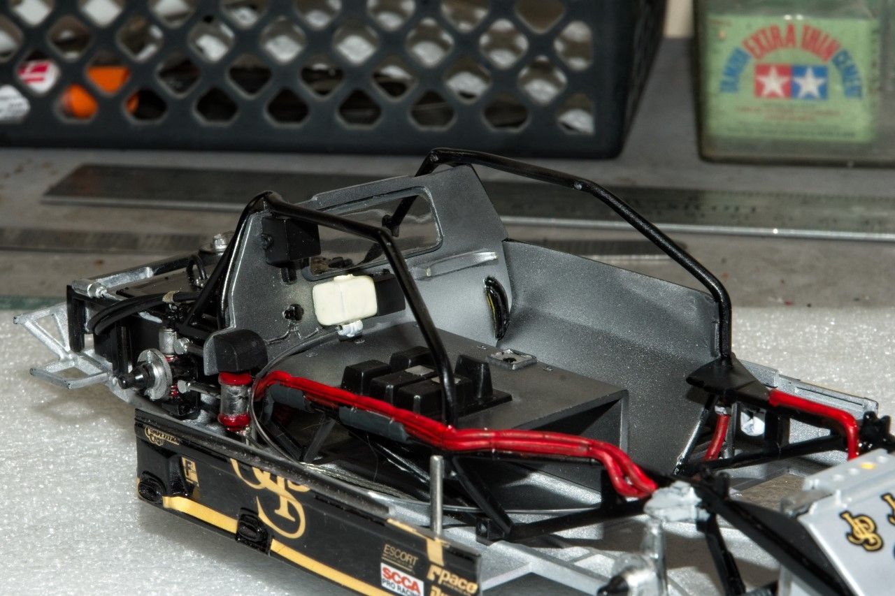
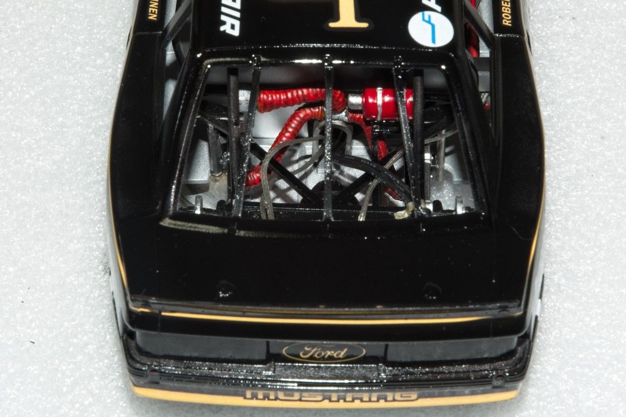
1st order of business was to glue the glass bukhead window in place, but 1st I had to paint the rubber glasket, which I did by hand painting Tamiya XF-69 Nato Black, then gluing it in place with Tamiya Extra Thin. Then glue the driver's compartment rear bulkhead to the chassis tubing. Turned out to be another gluing adventure. Only this time it was all my fault. The tubing is super glossy, and not even Tamiya Extra Thin would eat through all the layers of Tamiya X-1 Gloss Black. Then I tried CA glue, and it was basically another failure as it held, but would snap right off while working on the interior. So out came the 5 min Epoxy, a little scraping of the tubing, and the job was done.


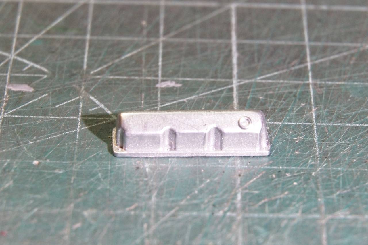
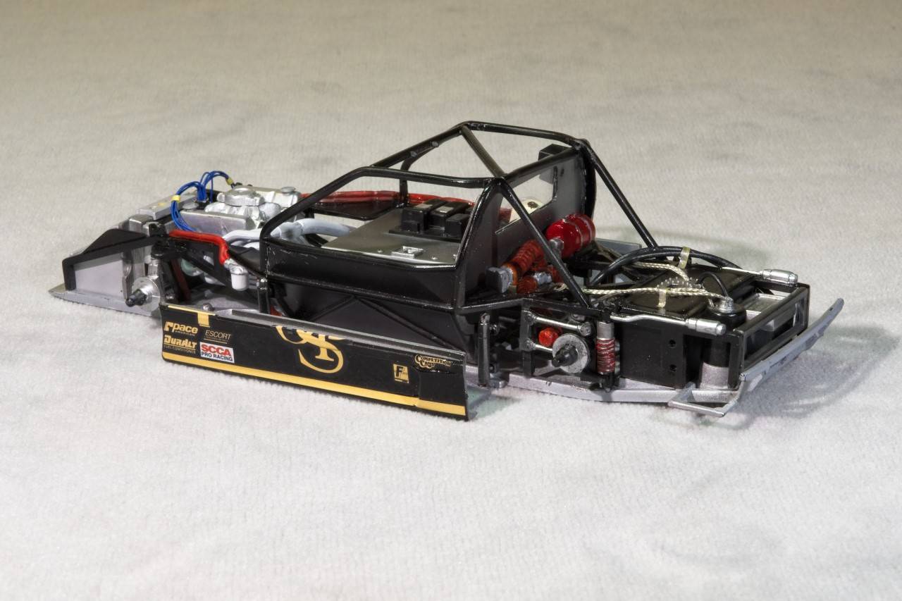
Now my undivided attention was focused on the engine/transmission sub assembly. The Roush Ford 358 ci V8 engine developed 650 hp running a single 4 barrel carb, and a Oil Dry Sump system. The kit parts fit basically well enough so that assembly was straight forward. However, the valve covers are the wrong ones, but I didn't have any spares so I used them with one modification. The breathers are just represented by a small raised circle?:


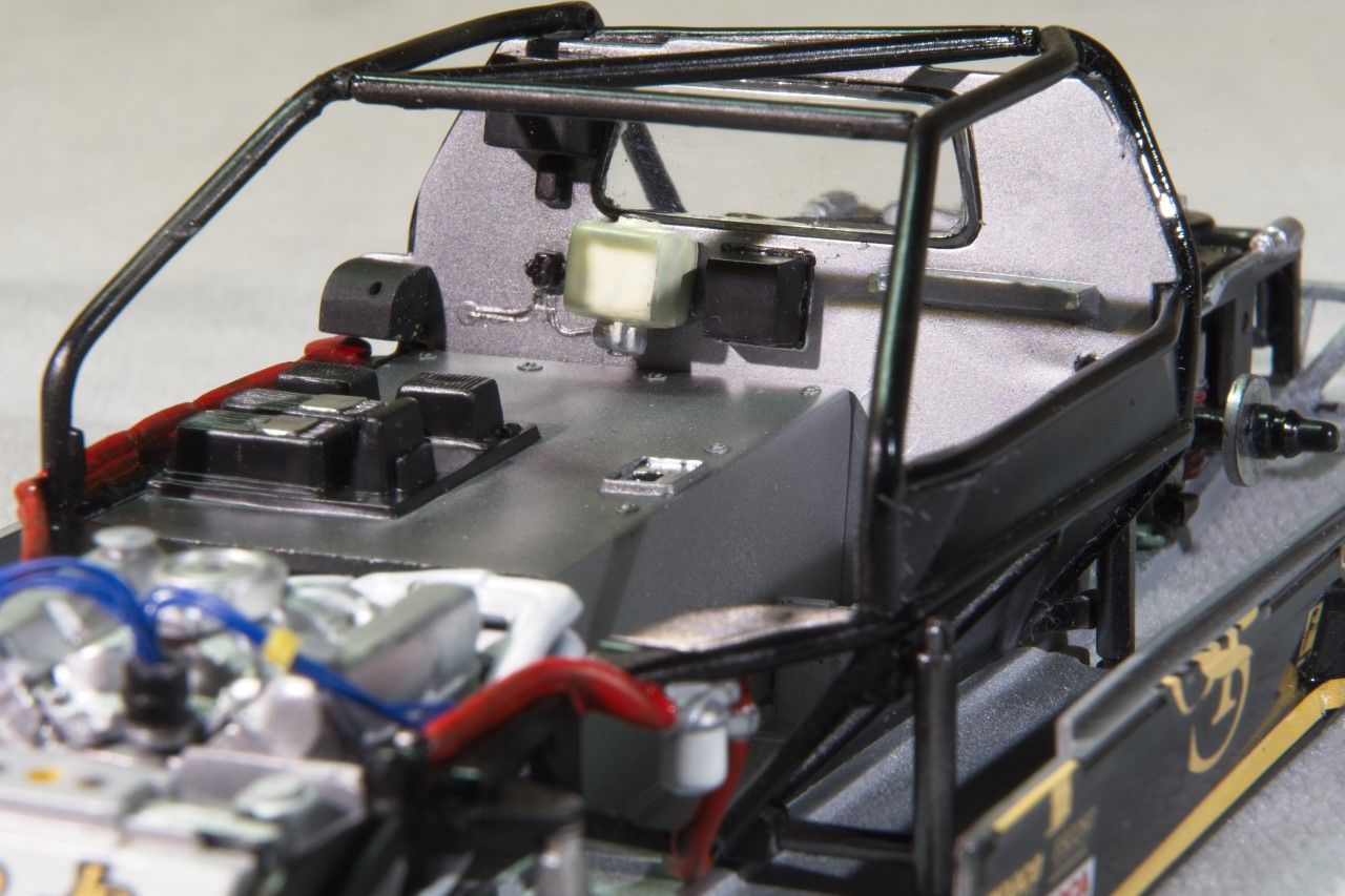
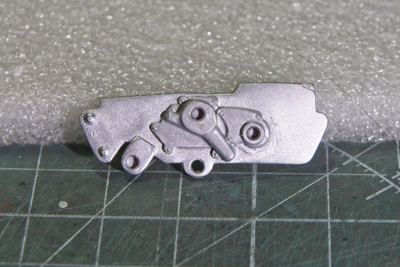
The Alloy Aluminum front plate was used as the main attachment points for the engine to the chassis, had some vaguely molded on parts that represented the ignigion coil and an over flow bottle. I just cut, filed, and sanded them off. I air brushed the plate Mr. Color Metalizer Steel, and then painted the water pump flat Aluminum. Unfortunately, I've never been able to really photograph the various shades of Aluminum Metalizer so that it looks like it does in person. This is the best I could do.


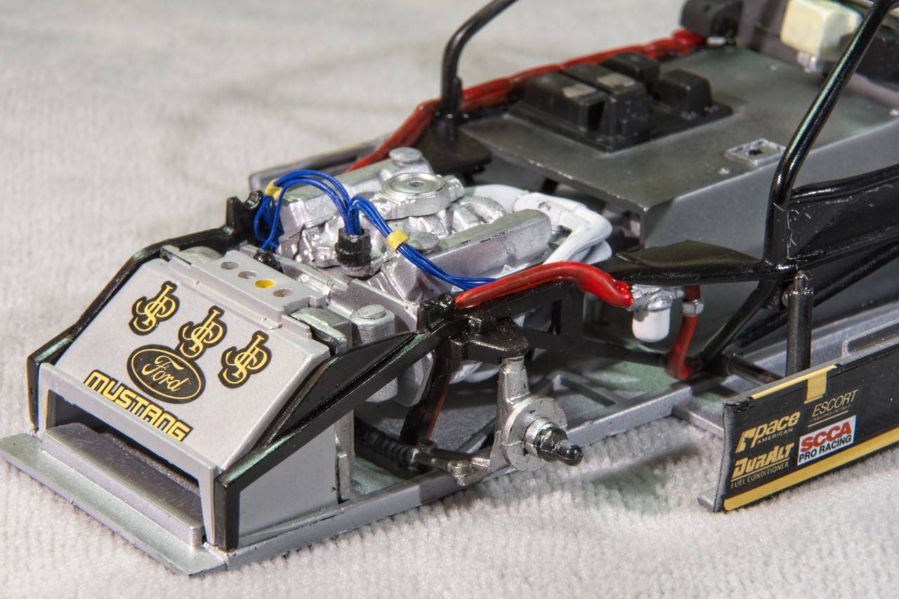
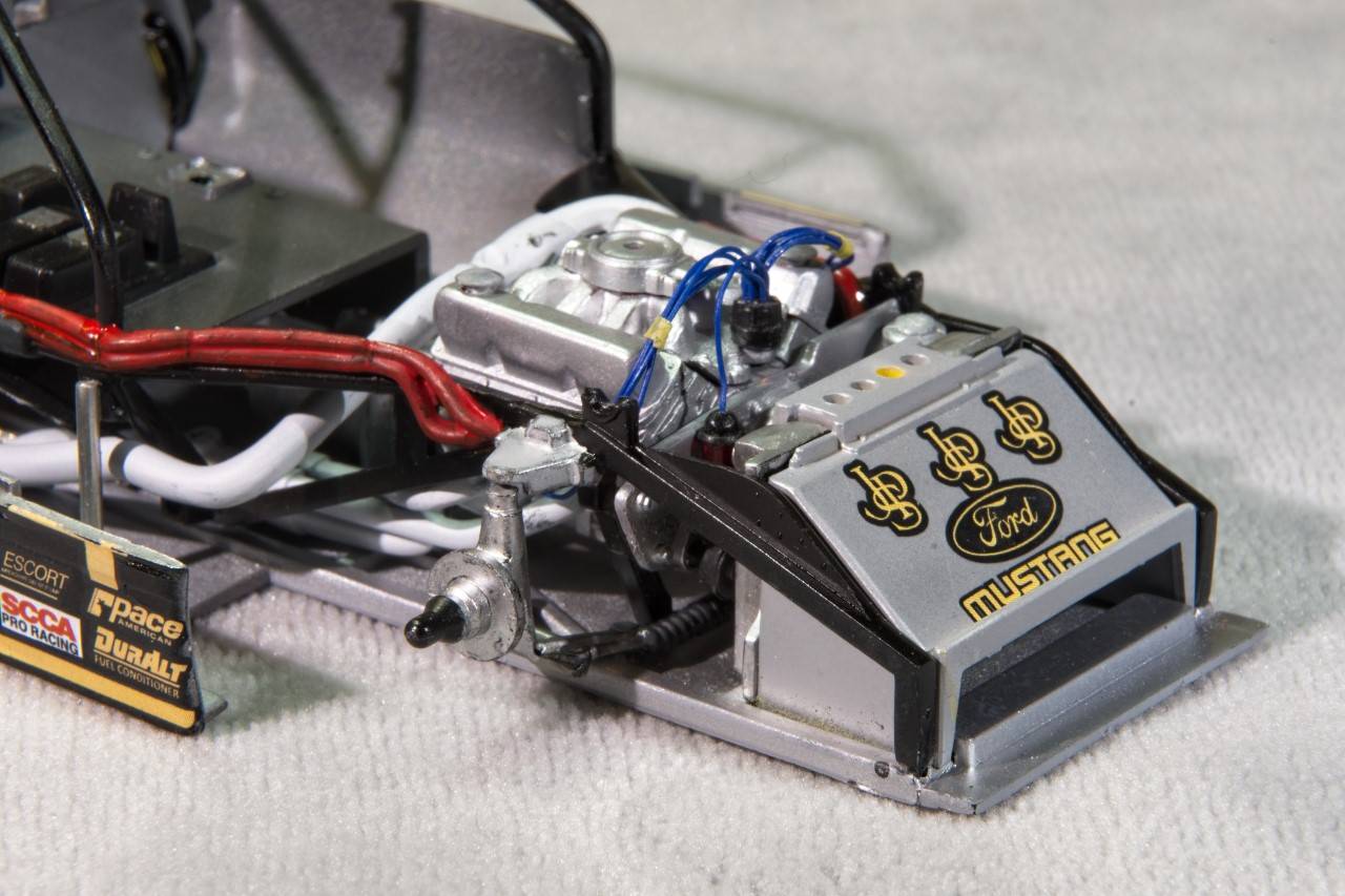
I made a ignition coil out of Evergreen tubing, and a little putty that was sanded to shape to represent the cone top. I used a generic bottle to represent the overflow bottle from my spares box. Unfortunately, I just forgot to photograph the assembly before installing the engine. I drilled out the distributor, and glued 9 Blue ignition wires for the plugs plus the one for the coil. Then glued the wires in place. The ignition wires are strapped and attached to the front of the valve covers on the real engine. I've wrapped them, but haven't as yet glued the wrap to the valve covers. I also used bits & pcs to make the breathers for the valve covers. If you look at the front of the engine, you can see the Aluminum mounting plate and on one side the over flow bottle, and on the other side the top of the coil with the ignition wire. You can also see that both Valve covers have a breathers made from more bits & pcs.

As for getting the engine/trans installed as it's a super tight fit was a major squeeze job, but ventually it does fit.


I didn't bother doing anthing with the carb other then gluing it on the top of the intake manifold as it will be completely covered by the air filter to be attached later. It's really more of a spacer then anything else.

As for the engine exhaust manifolds, they're each a 2 pc assembly that did require some putty and sanding. Then they were painted using the "Neat" method of no thinner so that it had a really rough texture to it. Installation was shall I say a little sloppy at best, but I did manage to get both installed and aligned, as well as the exhaust pipes which don't rearch the body panels. No big deal in my build as you can't see them once the main body is on. There is still a cross over pipe that I need to install to complete the engine exhaust system.

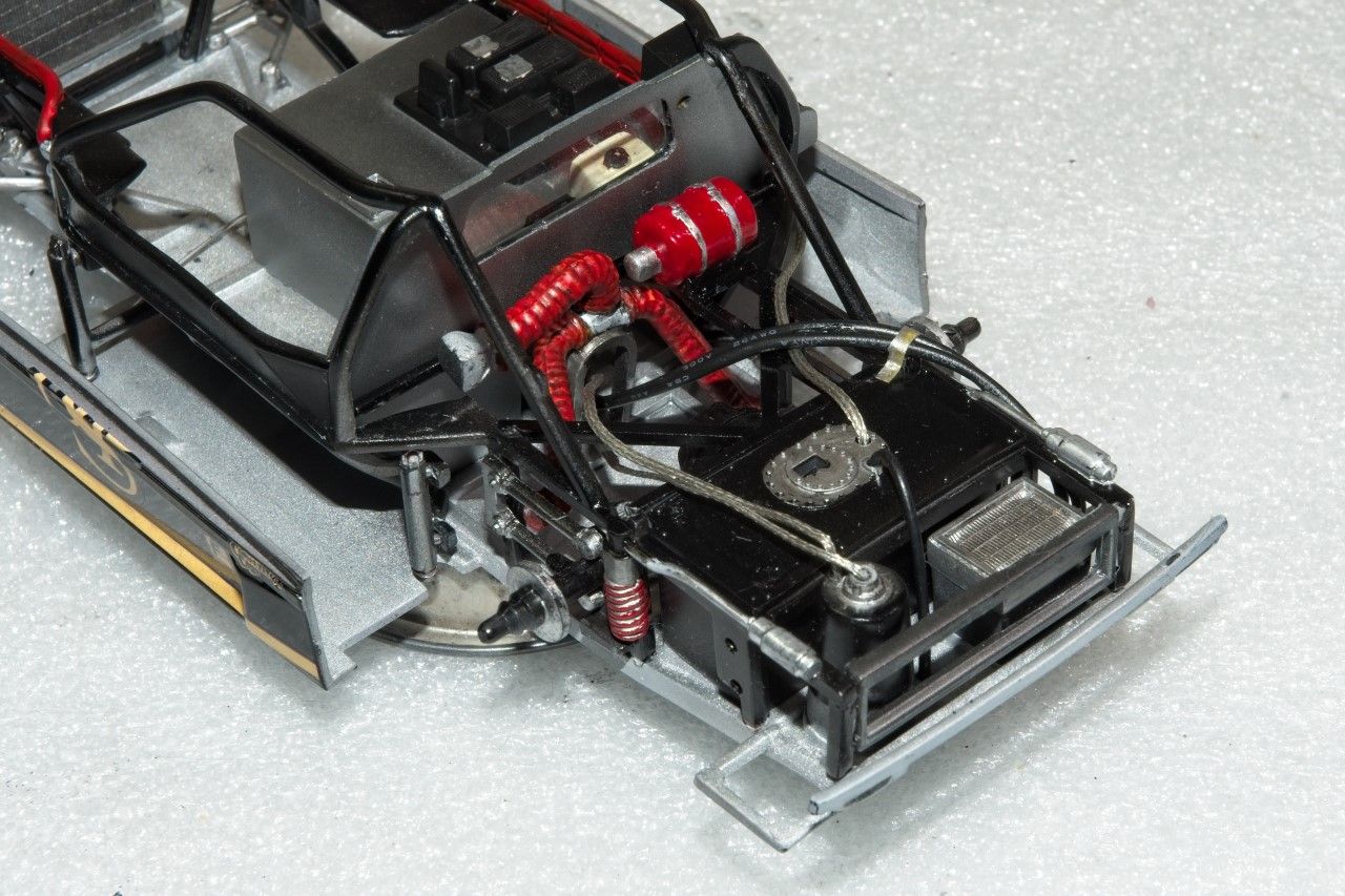
Originally I was going to add more lines to the engine compartment, but it's pretty tight with the engine installed, so this is going to be it unless I figure how to add a line here and there.

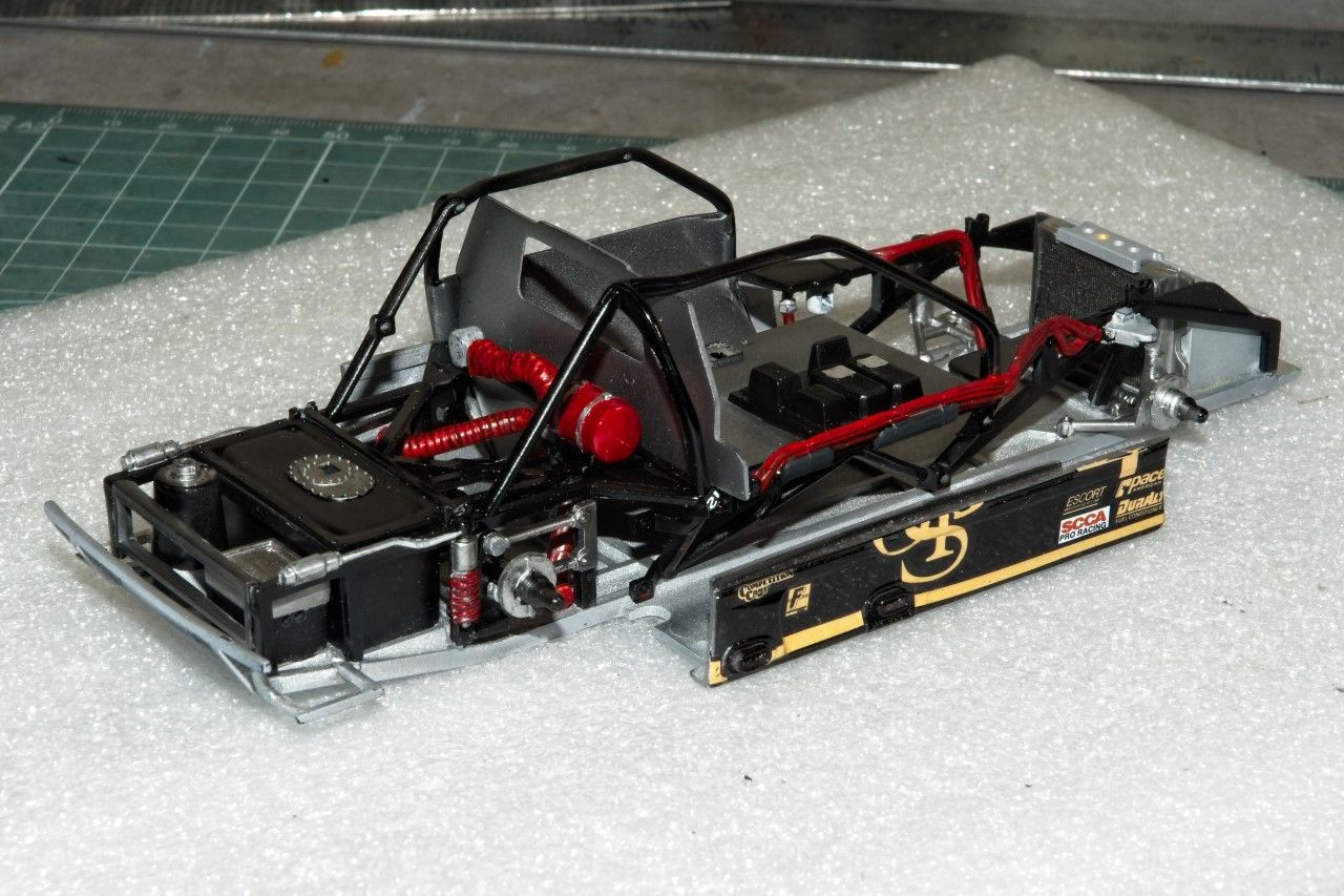
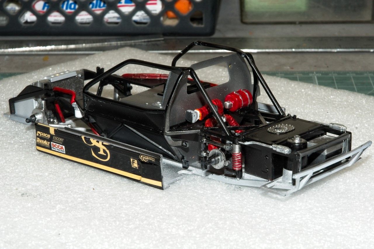
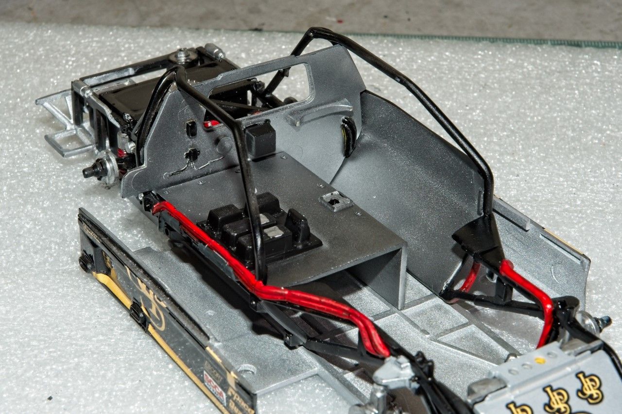
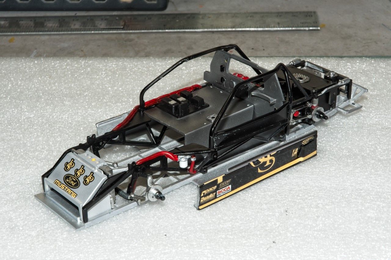
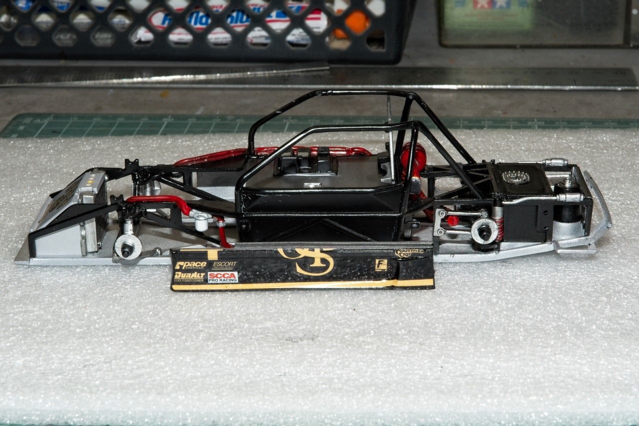
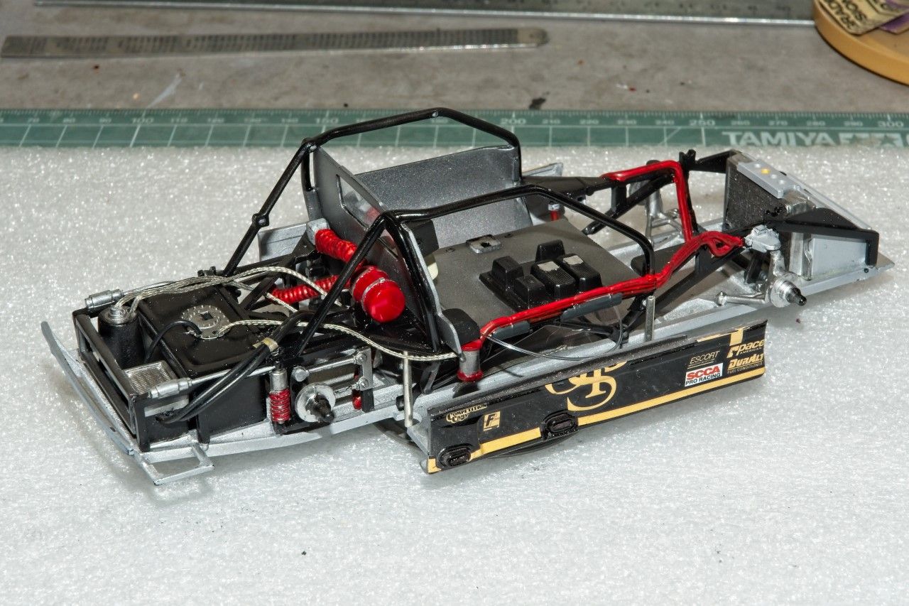
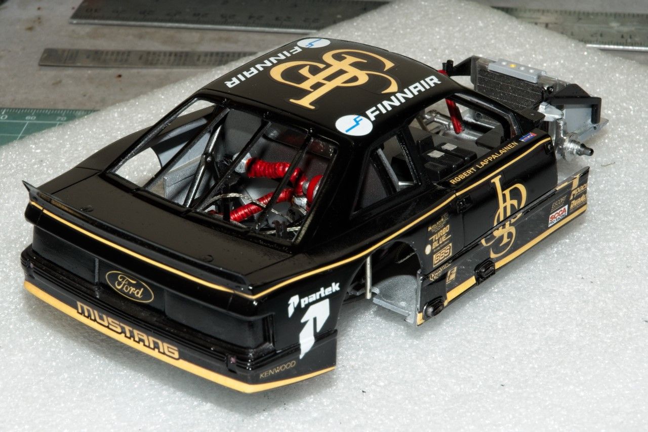
Here' a few pictures of the overall chassis assembly to date:


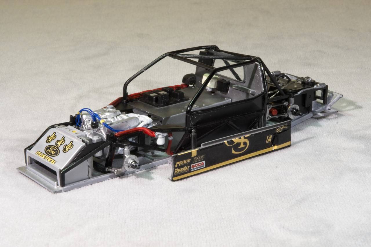
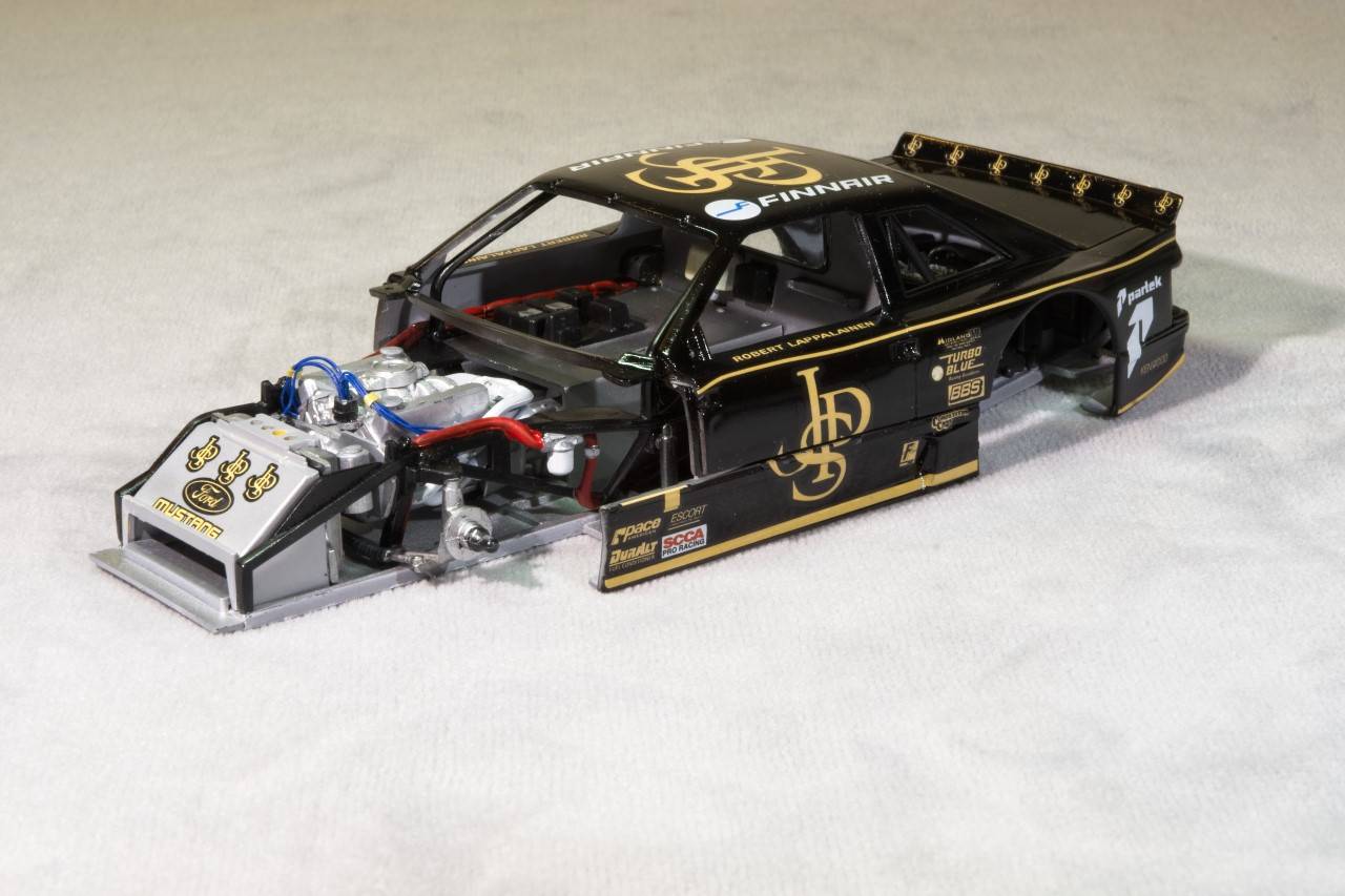
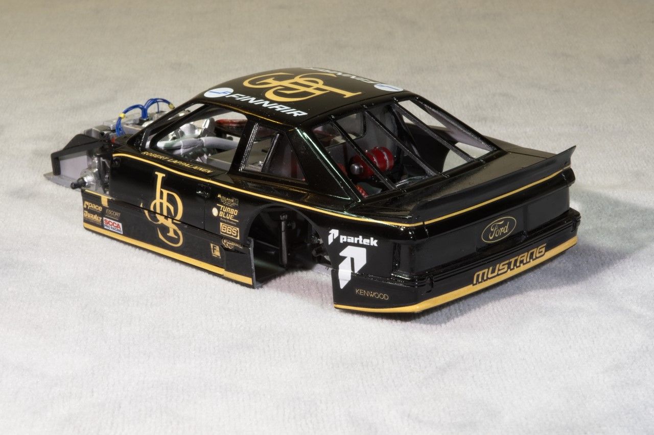
And 2 pics with the rear shell just dry fitted. Of course it's out of alignment as I must have done that while placing the chassis for pictures.


Thanks for taking the time to check out my build to date, it's always much appreciated.

Joel


RussellE
#306
_VISITCOMMUNITY
Victoria, Australia
Joined: June 27, 2010
KitMaker: 3,959 posts
Auto Modeler: 495 posts
Posted: Sunday, December 08, 2019 - 11:12 PM UTC
Joel, your persistence with this kit is definitely paying off!

Very nice details on the engine (leads etc) and it looks the part!

Going to be good to see the wheel/tire combo go on ready for the shell!