1911 Packard Tourer 1:32 scale
New South Wales, Australia
Joined: March 26, 2009
KitMaker: 366 posts
Auto Modeler: 19 posts
Posted: Sunday, June 13, 2010 - 01:17 AM UTC
Hi guys.
This is my first post here, I usually hang out at aeroscale where I build my 1:32 scale WW1 aircraft. I am doing a diorama for my aircraft and decided to add a same period car to the scene, finding cars in 1:32 scale for this era is pretty hard, and expensive. Anyhow, this is what I have done so far, not a lot but it is a start, remember, I am not a vehicle builder so please be kind............
I am doing a full build log of this car on my website.
http://www.ww1aircraftmodels.com Hope you find my little project interesting.
Any comments or suggestions will be greatly appreciated.
Des.
Check my site for 1:32 scale WW1 aircraft model build logs, build techniques, how to make turnbuckles and eyelets plus much more, plenty of photos of my finished models
AussieReg
 Associate Editor
#007
Victoria, Australia
Joined: June 09, 2009
KitMaker: 8,156 posts
Auto Modeler: 2,953 posts
Posted: Sunday, June 13, 2010 - 02:49 AM UTC
G'day Des. Love your work, I'll be watching this build right through.
Cheers, D
ON the bench
Revell 1/24 '53 Corvette (building as '54)
Revell 1/24 BMW 507 Coupe and Cabrio
Italeri 1/48 Me262 B-1a/U1 Nightfighter
Monogram 1/24 '57 Chevy Nomad
Dragon 1/350 USS Frank Knox DD-742
Grumpyoldman
_ADVISOR Florida, United States
Joined: October 17, 2003
KitMaker: 15,338 posts
Auto Modeler: 203 posts
Posted: Sunday, June 13, 2010 - 04:20 AM UTC
You certainly are off to an impressive start on this ancient kit.
Character is what you do when no one is looking.
Few things are harder to put up with than a good example.- Mark Twain
Make yourself an honest man, and then you may be sure that there is one less scoundrel in the world.--Thomas Carlyle
Myanmar
Joined: March 05, 2004
KitMaker: 4,011 posts
Auto Modeler: 851 posts
Posted: Sunday, June 13, 2010 - 04:24 AM UTC
I think I have that kit on the shelf somewhere. Great start with the details

i watched a scale plastic figure crawl along the edge . . . of an exacto blade . . . that's my dream , it's my nightmare . . . . . . . crawling , slithering . . . . . along the edge . . . . . . of an exacto . . . . . blade . . . . and surviving
New South Wales, Australia
Joined: March 26, 2009
KitMaker: 366 posts
Auto Modeler: 19 posts
Posted: Sunday, June 13, 2010 - 02:05 PM UTC
Thanks guys for your kind words.
Yes, it is an ancient kit, the lack of crankcase detail is testimony to that. The instruction sheet included with the kit is very faded and hard to read and there are no painting instructions at all. The kit was advertised as having brass plated parts, well, there isn't any, what supposed to be brass is only grey plastic, the remainder of the kit is black plastic. I will battle on.
Des.
http://www.ww1aircraftmodels.com Check my site for 1:32 scale WW1 aircraft model build logs, build techniques, how to make turnbuckles and eyelets plus much more, plenty of photos of my finished models
Kobenhavn, Denmark
Joined: June 29, 2004
KitMaker: 6,760 posts
Auto Modeler: 2,182 posts
Posted: Sunday, June 13, 2010 - 11:04 PM UTC
On the workbench:
MPC: 1972 Pontiac GTO
Revell: 1965 Mustang
Verlinden 120mm guard of the marine.
Revell: 2010 Camaro
Monogram: 1931 Rolls Royce
Italeri: LVT2 Amtrac
New South Wales, Australia
Joined: March 26, 2009
KitMaker: 366 posts
Auto Modeler: 19 posts
Posted: Wednesday, June 16, 2010 - 04:19 PM UTC
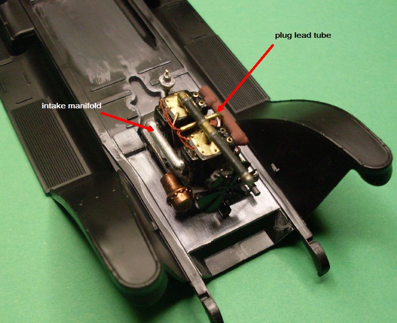
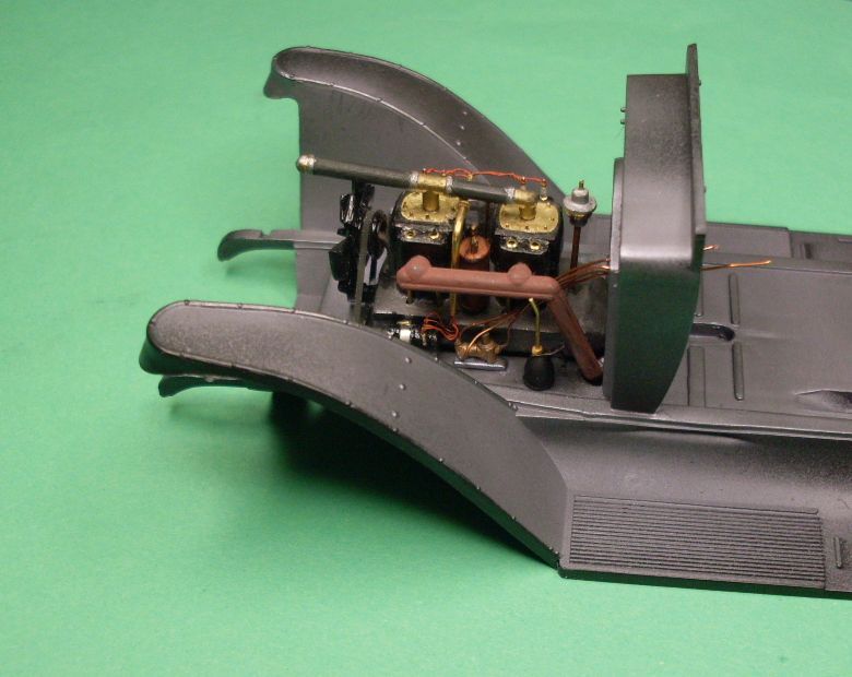
Just a quickie up-date. The engine is nearly completed, I sat it in the chassis just to see what it would look like. The plug leads are 0.13mm copper wire painted with Humbrol N0.100 red/brown and they run through a brass tube. The magneto is hand made from bits I had on hand. I made a pulley and fitted it behind the fan and also made a pulley and fitted it to the front of the crankcase. The fan belt is a piece of paper cut to the correct width, fitted, then painted with dark grey. Not a lot to report but at least it is a step forward.
I found the date moulded on one of the parts, 1967, so it is an ancient kit.
Des.
http://www.ww1aircraftmodels.com 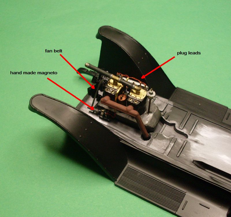
Check my site for 1:32 scale WW1 aircraft model build logs, build techniques, how to make turnbuckles and eyelets plus much more, plenty of photos of my finished models
AussieReg
Associate Editor #007
Victoria, Australia
Joined: June 09, 2009
KitMaker: 8,156 posts
Auto Modeler: 2,953 posts
Posted: Wednesday, June 16, 2010 - 05:59 PM UTC
Quoted Text
I found the date moulded on one of the parts, 1967, so it is an ancient kit.
Des.
Hey, ease up Des, I was born in '67. That makes it a superbly aged kit !!
As usual your work here in the detailing is excellent.
Cheers, D
ON the bench
Revell 1/24 '53 Corvette (building as '54)
Revell 1/24 BMW 507 Coupe and Cabrio
Italeri 1/48 Me262 B-1a/U1 Nightfighter
Monogram 1/24 '57 Chevy Nomad
Dragon 1/350 USS Frank Knox DD-742
New South Wales, Australia
Joined: March 26, 2009
KitMaker: 366 posts
Auto Modeler: 19 posts
Posted: Saturday, September 04, 2010 - 10:27 PM UTC
Sorry for the length of time between posts but I was obligated to build a Spad and do a full build log not only for my own website but for Aeroscale and theaerodromeforum.
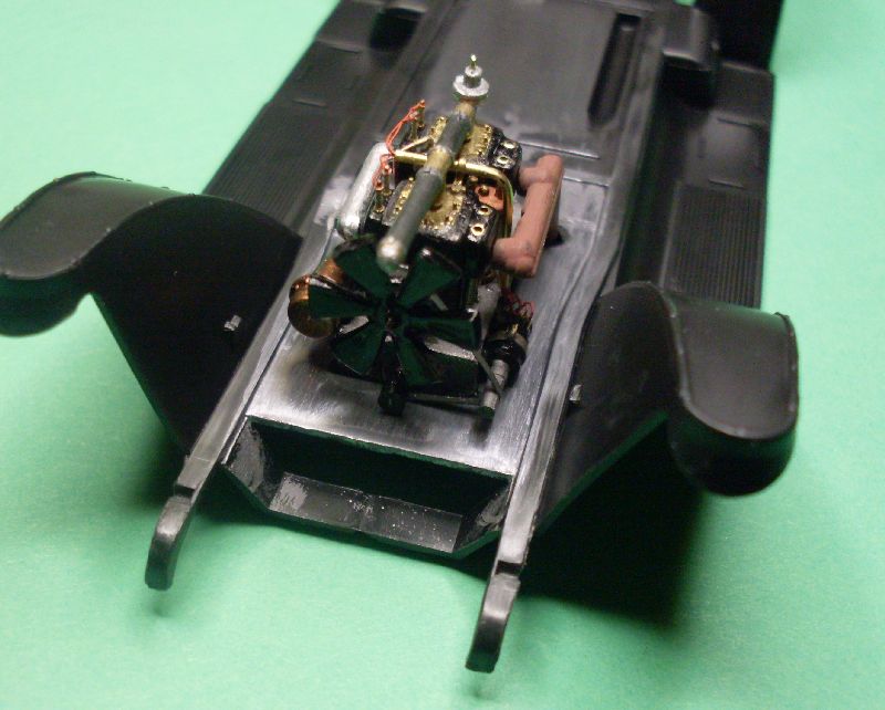
Photos I have seen of this car shows an oil can placed inside the engine bay near the exhaust, so I made an oil can from scrap bits and pieces. The second photo shows the oil can in the position it will eventually be fixed. I painted the engine bay floor and the firewall with Humbrol Polished Steel and buffed it to a semi gloss finish.
Des.
http://www.ww1aircraftmodels.com 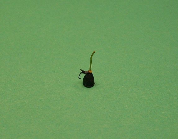
Check my site for 1:32 scale WW1 aircraft model build logs, build techniques, how to make turnbuckles and eyelets plus much more, plenty of photos of my finished models
New South Wales, Australia
Joined: March 26, 2009
KitMaker: 366 posts
Auto Modeler: 19 posts
Posted: Sunday, September 05, 2010 - 12:18 AM UTC
This photo shows a size comparison of the oil can that I made. The body is made from a shaped piece of plastic sprue, the tube is 0.4mm brass tube and the handle is made from PE fret material, a small plastic disc is glued to the bottom.
Des.
http://www.ww1aircraftmodels.com 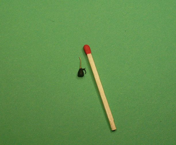
Check my site for 1:32 scale WW1 aircraft model build logs, build techniques, how to make turnbuckles and eyelets plus much more, plenty of photos of my finished models
Joined: December 15, 2002
KitMaker: 4,503 posts
Auto Modeler: 217 posts
Posted: Sunday, September 05, 2010 - 04:13 AM UTC
You have my undivided attention on this build. The detail is fantastic!!

Dave
"Don't be afraid to think outside the box"
"Animal wants Trucks!!"
Zuid-Holland, Netherlands
Joined: January 08, 2005
KitMaker: 1,066 posts
Auto Modeler: 234 posts
Posted: Sunday, September 05, 2010 - 09:23 AM UTC
This is going to look good

Currently on the bench:
Revell 1/25 Corvette C6
Revell 1/25 Dodge Viper SRT10
Tamiya 1/12 Honda CBR 1100 XX Super Blackbird
Tamiya 1/24 Opel Astra V8 Coupe Team Holzer
Tamiya 1/24 Volkswagen Karmann Ghia
Kobenhavn, Denmark
Joined: June 29, 2004
KitMaker: 6,760 posts
Auto Modeler: 2,182 posts
Posted: Sunday, September 05, 2010 - 11:10 PM UTC
Please dont let us wait another 3 months for the next update
Looks great Des.
On the workbench:
MPC: 1972 Pontiac GTO
Revell: 1965 Mustang
Verlinden 120mm guard of the marine.
Revell: 2010 Camaro
Monogram: 1931 Rolls Royce
Italeri: LVT2 Amtrac
New South Wales, Australia
Joined: March 26, 2009
KitMaker: 366 posts
Auto Modeler: 19 posts
Posted: Friday, September 17, 2010 - 10:51 PM UTC
I've been working on the interior of the vehicle. The large box is made from timber and stained with Jarrah wood stain. The two switches are made from scrap plastic and brass tube then painted with gold leaf. All the instruments are made from different size brass tube and finished off with instrument face decals, a drop of clear gloss acts as the glass. I have cut slots in the floor ready for the control pedals. I'm using a photo I downloaded from the net of a restored Packard so the accuracy may not be correct.
Des.
http://www.ww1aircraftmodels.com 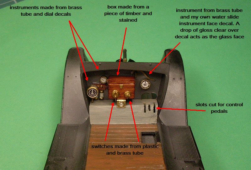
Check my site for 1:32 scale WW1 aircraft model build logs, build techniques, how to make turnbuckles and eyelets plus much more, plenty of photos of my finished models
New South Wales, Australia
Joined: March 26, 2009
KitMaker: 366 posts
Auto Modeler: 19 posts
Posted: Wednesday, September 22, 2010 - 11:40 PM UTC
Another up-date on progress so far.
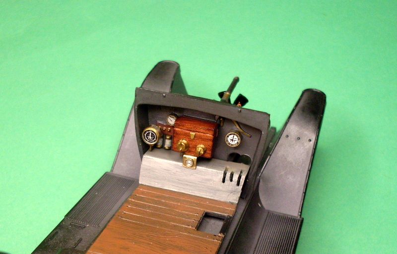
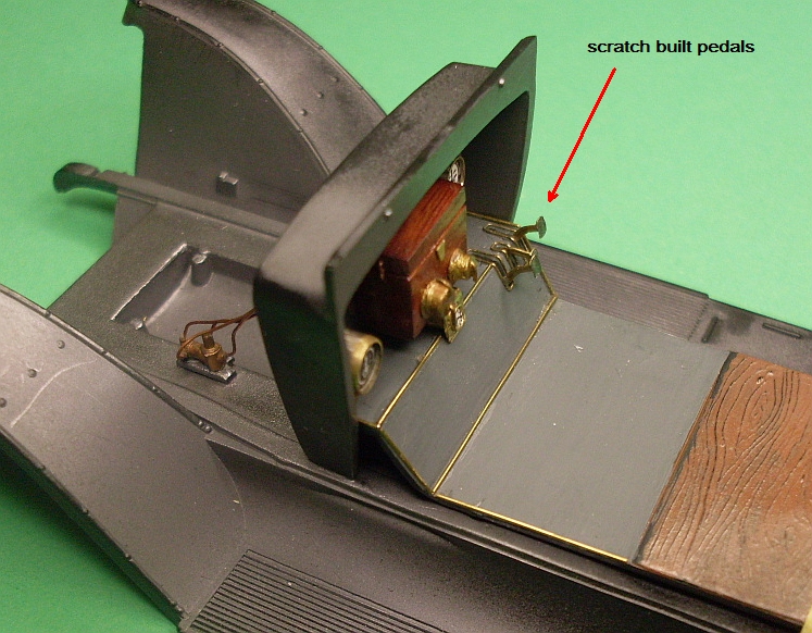
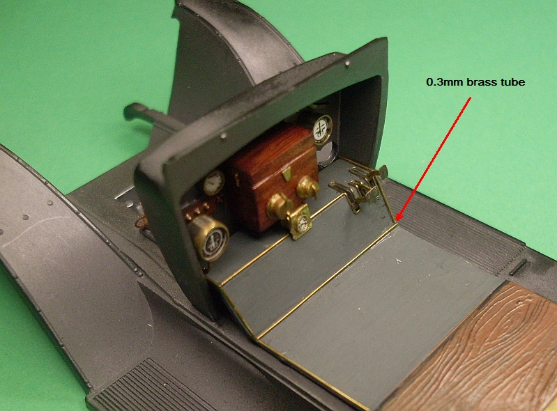
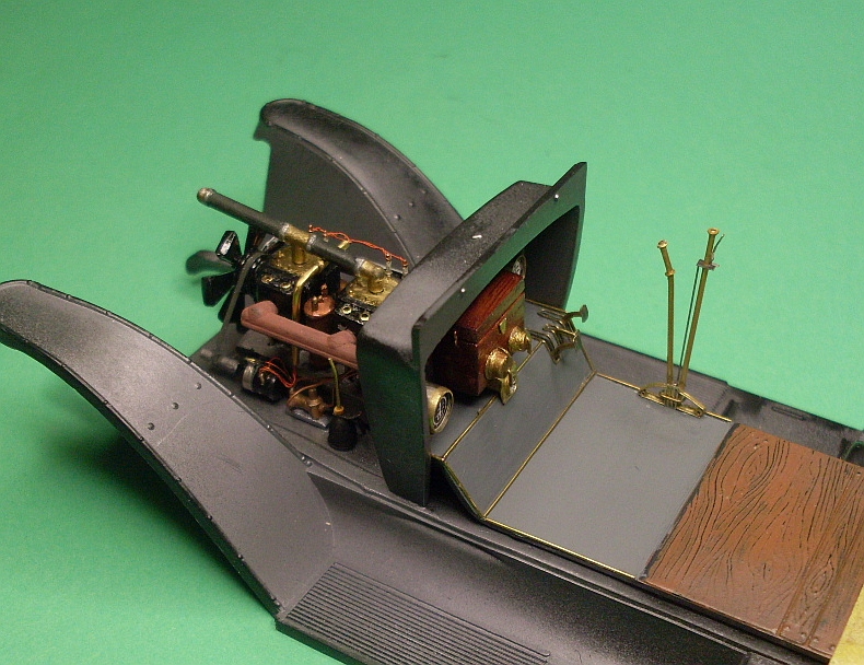
I made the foot pedals from 0.5mm brass tube bent to shape then flattened, the foot pads are made from left over PE fret material, CA holds everything in place. The brass edgings around the foot pedal cut out slots are made from 0.18mm brass wire bent to shape and held with CA. The floor edging is 0.3mm brass tube glued into position. The first photo clearly shows the scratch built switches and instruments plus the wooden box.
Des.
http://www.ww1aircraftmodels.com 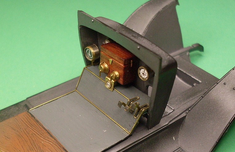
Check my site for 1:32 scale WW1 aircraft model build logs, build techniques, how to make turnbuckles and eyelets plus much more, plenty of photos of my finished models
New South Wales, Australia
Joined: March 26, 2009
KitMaker: 366 posts
Auto Modeler: 19 posts
Posted: Friday, September 24, 2010 - 12:47 AM UTC
I've started work on the gear and brake levers, the kit supplied item is way over size and bulky. I used 0.6mm brass tube to make the levers and added small brass washers for the hand stops. The small ratchet release lever is made from left over PE fret material and super glued to the lever. I still need to make the gate which will mount to the floor and encase the levers.
Des.
a full build log of this vehicle can be found on my website
http://www.ww1aircraftmodels.com 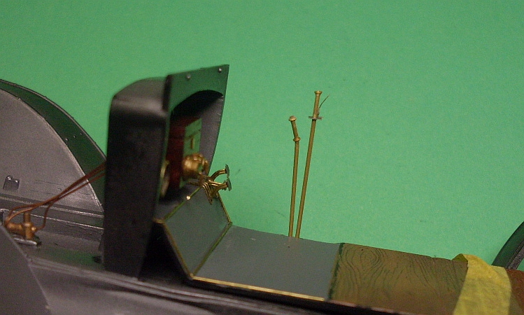
Check my site for 1:32 scale WW1 aircraft model build logs, build techniques, how to make turnbuckles and eyelets plus much more, plenty of photos of my finished models
Myanmar
Joined: March 05, 2004
KitMaker: 4,011 posts
Auto Modeler: 851 posts
Posted: Friday, September 24, 2010 - 01:50 PM UTC
Wow you're really going all the way with this one. Looking great
i watched a scale plastic figure crawl along the edge . . . of an exacto blade . . . that's my dream , it's my nightmare . . . . . . . crawling , slithering . . . . . along the edge . . . . . . of an exacto . . . . . blade . . . . and surviving
New South Wales, Australia
Joined: March 26, 2009
KitMaker: 366 posts
Auto Modeler: 19 posts
Posted: Sunday, September 26, 2010 - 12:11 AM UTC
I made the brake and gear lever gate from scrap brass, the main body is flattened 0.5mm brass tube. The ratchet release rod is a worn out 0.2mm drill bit held in place with CA.
Des.
http://www.ww1aircraftmodels.com 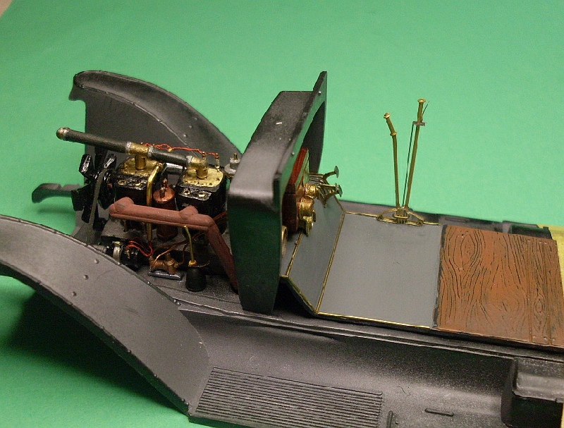
Check my site for 1:32 scale WW1 aircraft model build logs, build techniques, how to make turnbuckles and eyelets plus much more, plenty of photos of my finished models
United States
Joined: June 26, 2010
KitMaker: 7 posts
Auto Modeler: 1 posts
Posted: Sunday, September 26, 2010 - 02:59 AM UTC
Well Done!!!!!!!!!!!!!!!!!!!!!!!!!!!!!!!!!!!!
Kobenhavn, Denmark
Joined: June 29, 2004
KitMaker: 6,760 posts
Auto Modeler: 2,182 posts
Posted: Monday, September 27, 2010 - 11:06 PM UTC
I'm getting more and more impressed with every update. Amazing.
On the workbench:
MPC: 1972 Pontiac GTO
Revell: 1965 Mustang
Verlinden 120mm guard of the marine.
Revell: 2010 Camaro
Monogram: 1931 Rolls Royce
Italeri: LVT2 Amtrac
New South Wales, Australia
Joined: March 26, 2009
KitMaker: 366 posts
Auto Modeler: 19 posts
Posted: Monday, September 27, 2010 - 11:53 PM UTC
Thanks guys for all your nice comments, they are much appreciated.
The kit supplied steering wheel is a very poor representation of the real thing so I have decided to make a new one. I removed the spokes and utilised the outer rim, I also reused the hub. The spokes are made from thin brass sheet bent to the appropriate shape then super glued to the hub and rim. I still need to add the ignition advance/retard lever plus the guide rail for the lever, this will span three spokes. The photo shows a trial fit of the unfinished steering wheel.
Des.
http://www.ww1aircraftmodels.com 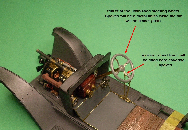
Check my site for 1:32 scale WW1 aircraft model build logs, build techniques, how to make turnbuckles and eyelets plus much more, plenty of photos of my finished models
New South Wales, Australia
Joined: March 26, 2009
KitMaker: 366 posts
Auto Modeler: 19 posts
Posted: Tuesday, September 28, 2010 - 10:13 PM UTC
Another quickie update. Here is a photo of the near completed steering wheel, I still need to add the wood grain to the rim.
(Sorry to burden you with such minor details but I love doing this sort of work.)
Des.
http://www.ww1aircraftmodels.com 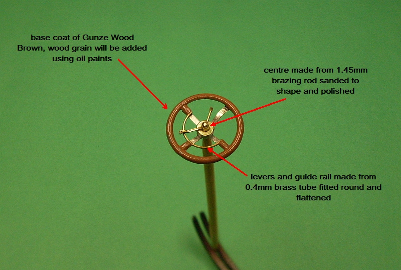
Check my site for 1:32 scale WW1 aircraft model build logs, build techniques, how to make turnbuckles and eyelets plus much more, plenty of photos of my finished models
Kobenhavn, Denmark
Joined: June 29, 2004
KitMaker: 6,760 posts
Auto Modeler: 2,182 posts
Posted: Tuesday, September 28, 2010 - 11:07 PM UTC
Quoted Text
(Sorry to burden you with such minor details but I love doing this sort of work.)
Definitely not a burden. I love to see this sort of work
Keep'em coming.
On the workbench:
MPC: 1972 Pontiac GTO
Revell: 1965 Mustang
Verlinden 120mm guard of the marine.
Revell: 2010 Camaro
Monogram: 1931 Rolls Royce
Italeri: LVT2 Amtrac
New South Wales, Australia
Joined: March 26, 2009
KitMaker: 366 posts
Auto Modeler: 19 posts
Posted: Saturday, October 02, 2010 - 09:09 PM UTC
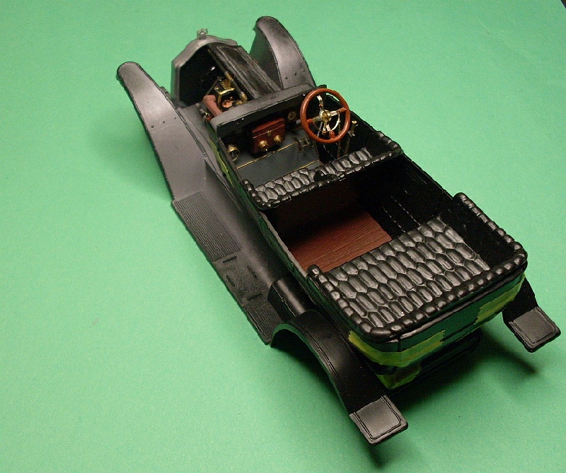
The first two photos show a mock up of the body. The steering wheel is now completed and is just sitting loose on the steering column. The right side engine bonnets will be fixed closed while the left side will be hinged open to display the engine.
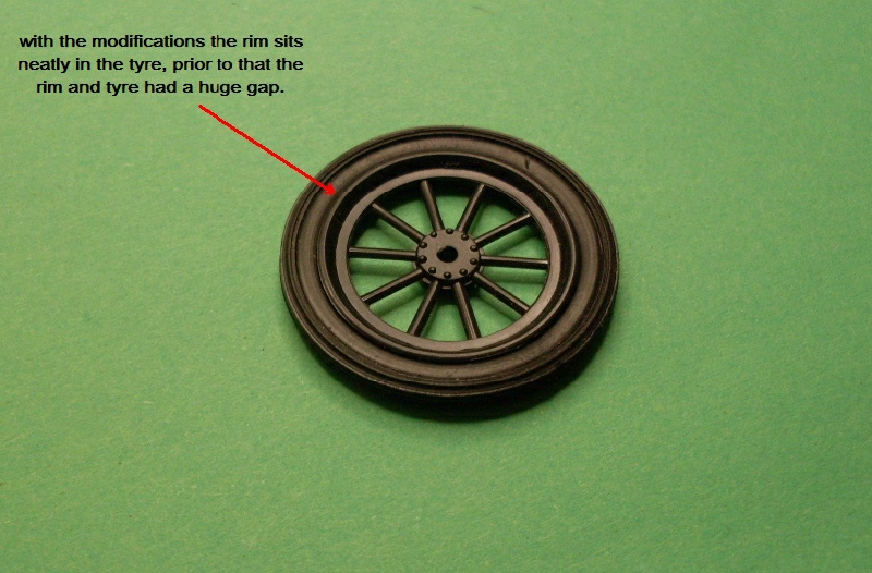
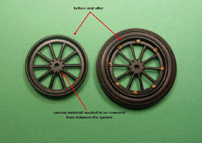
The third photo shows a rim fitted to one of the tyre, I had to remove the inside lip of the tyre so the rim would fit, I also had to modify the inside of the rim so it sat tight against the tyre. The tyres are a very poor rubber moulding with a lot of clean up required, hopefully they will look ok when the rims are painted.
Des.
A full build log can be found on my website;
www.ww1aircraftmodels.com 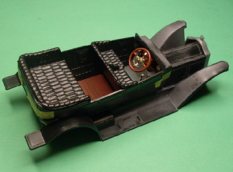
Check my site for 1:32 scale WW1 aircraft model build logs, build techniques, how to make turnbuckles and eyelets plus much more, plenty of photos of my finished models
New South Wales, Australia
Joined: March 26, 2009
KitMaker: 366 posts
Auto Modeler: 19 posts
Posted: Thursday, October 07, 2010 - 10:02 PM UTC
I added the rim/tyre locking plates and bolts to one wheel, three to go. I used the Vectorcut nut and bolt set to make the plates. I trimmed one side off the nut to give a flat side to sit against the rim, super glue holds them extremely well. I drilled a 0.5mm hole through the rim then inserted a short length of 0.5mm brass tube to simulate the bolt. The photos show the unpainted rim but the completed locking plates and bolts, these will be painted as well.
Des.
http://www.ww1aircraftmodels.com 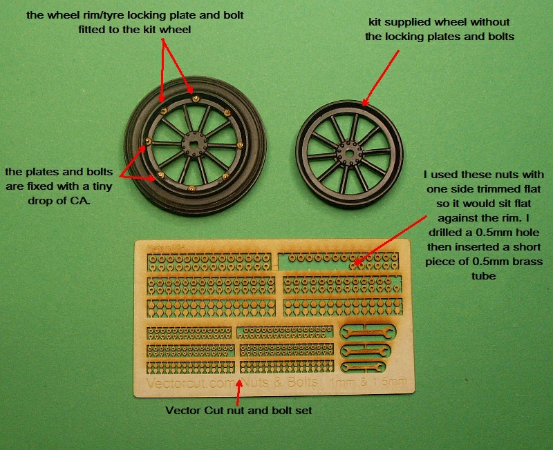
Check my site for 1:32 scale WW1 aircraft model build logs, build techniques, how to make turnbuckles and eyelets plus much more, plenty of photos of my finished models